Is it OK to (mis?)use pins for playing role of GND and VCC?

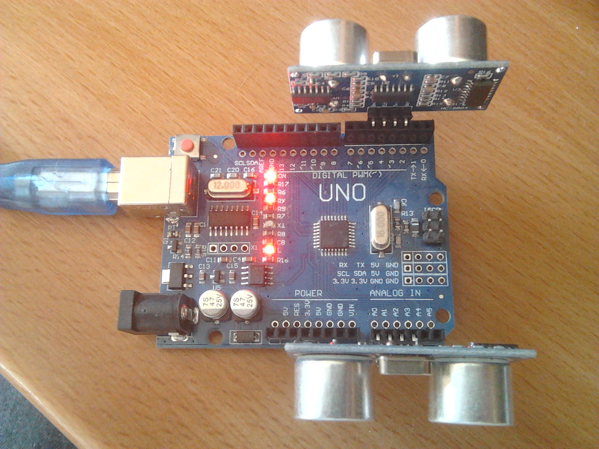
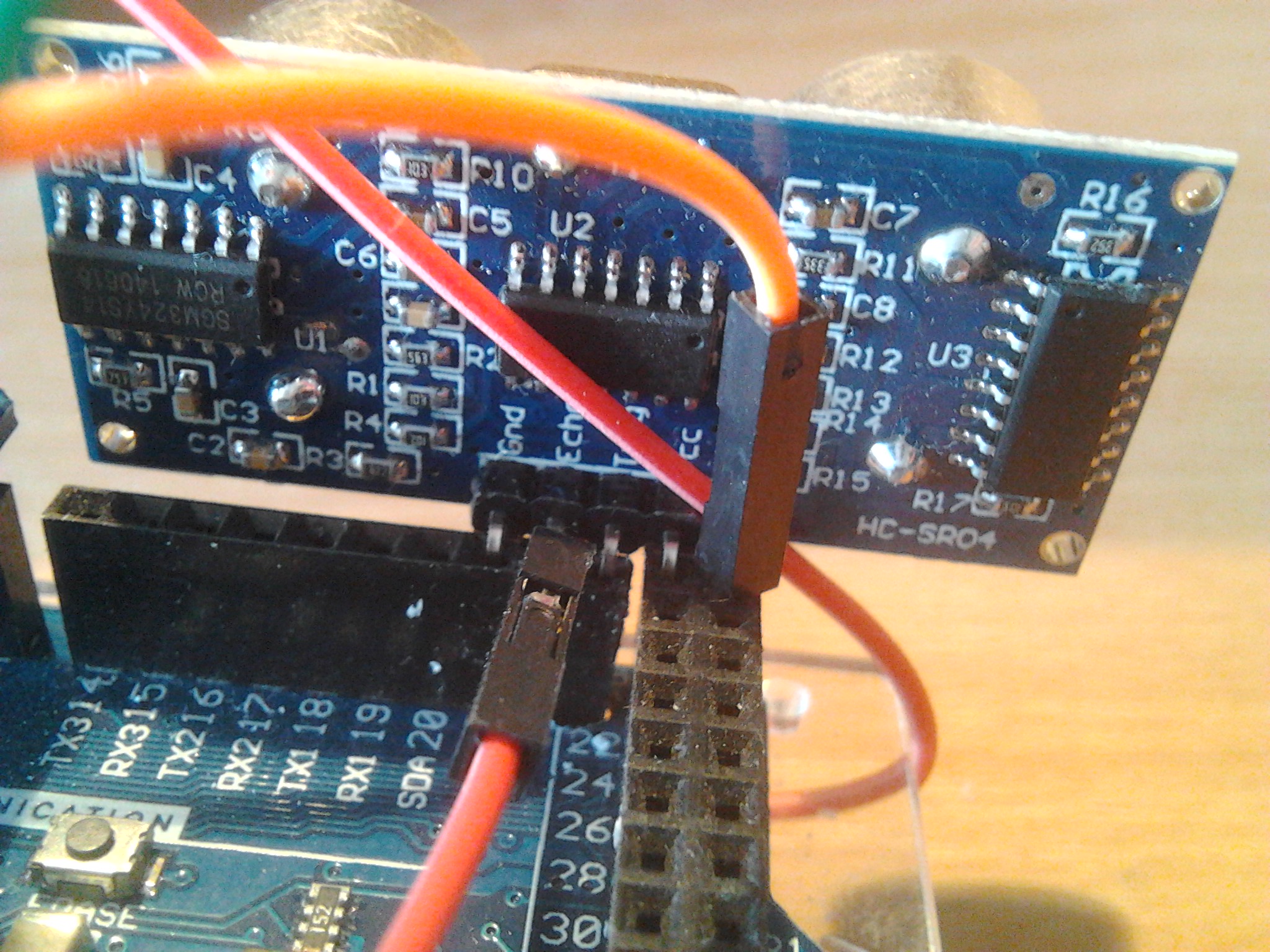
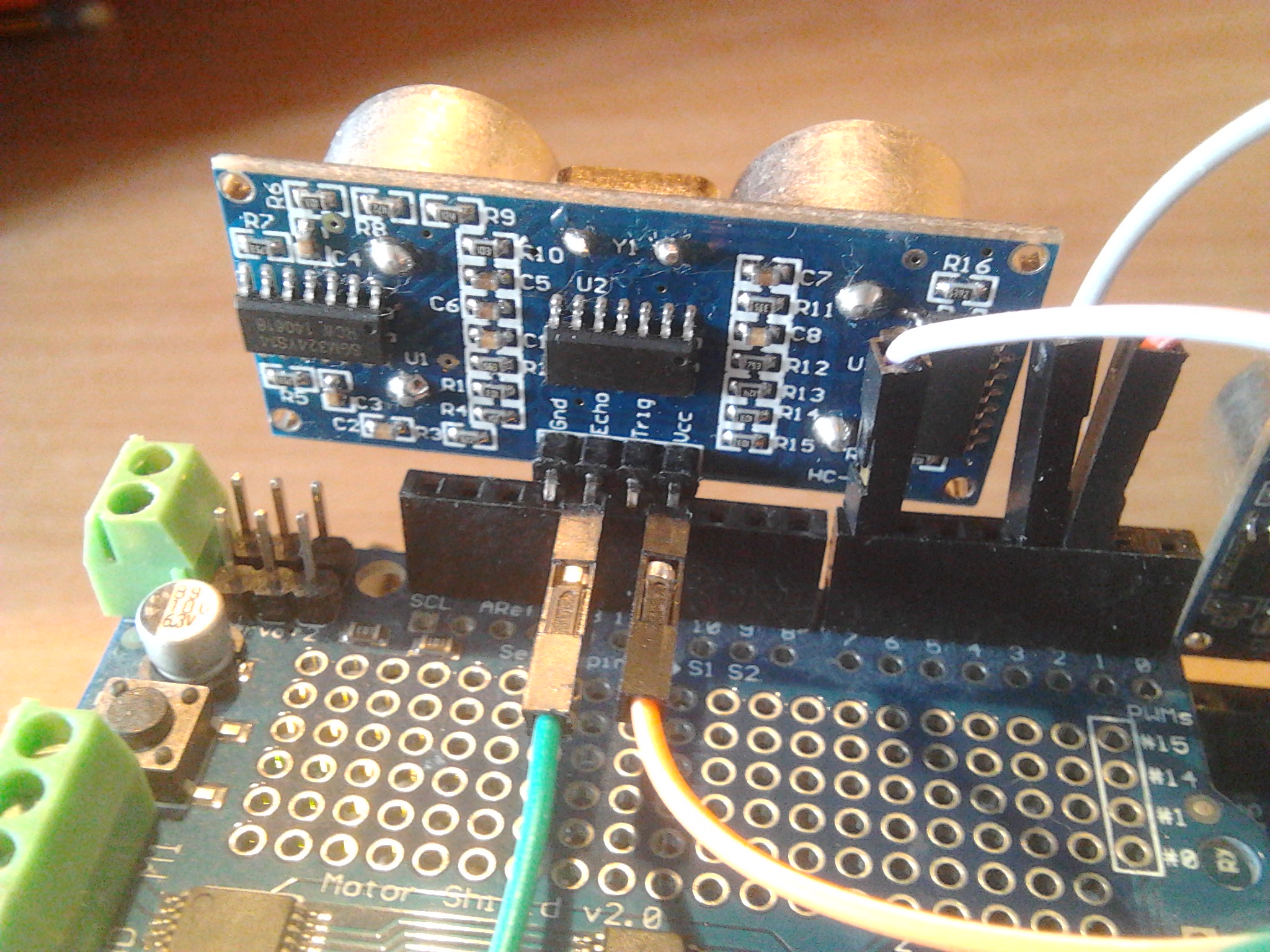
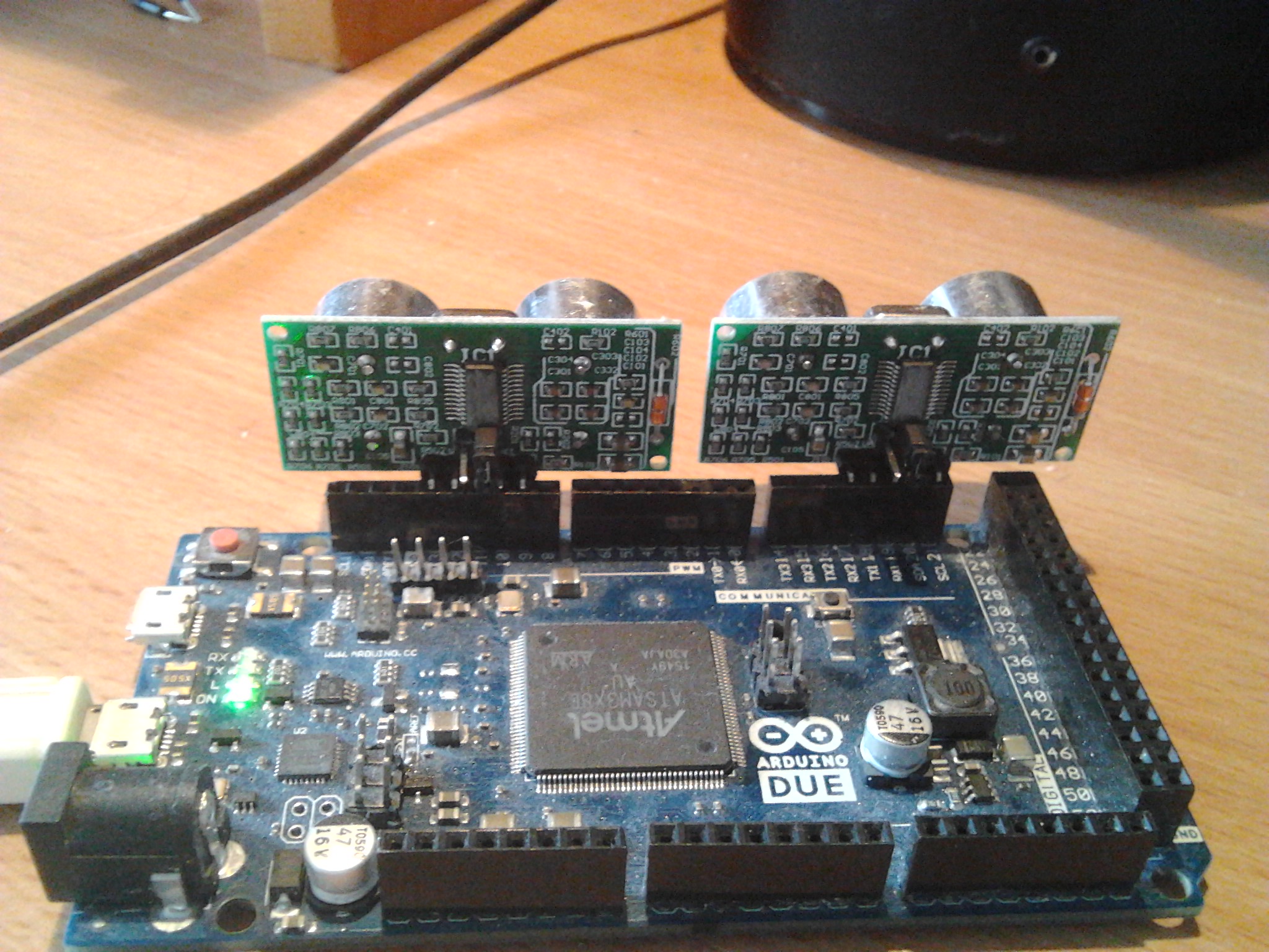
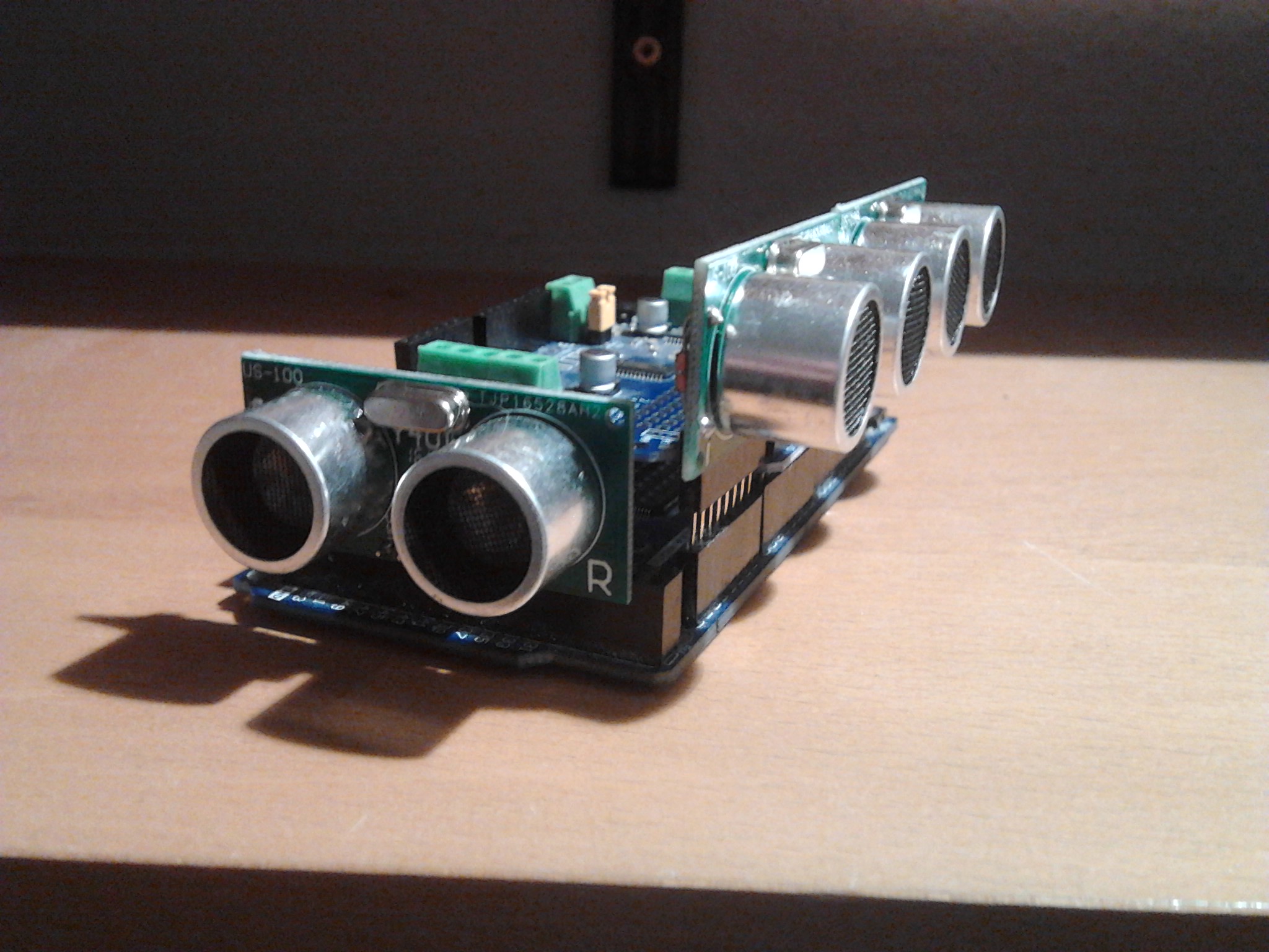
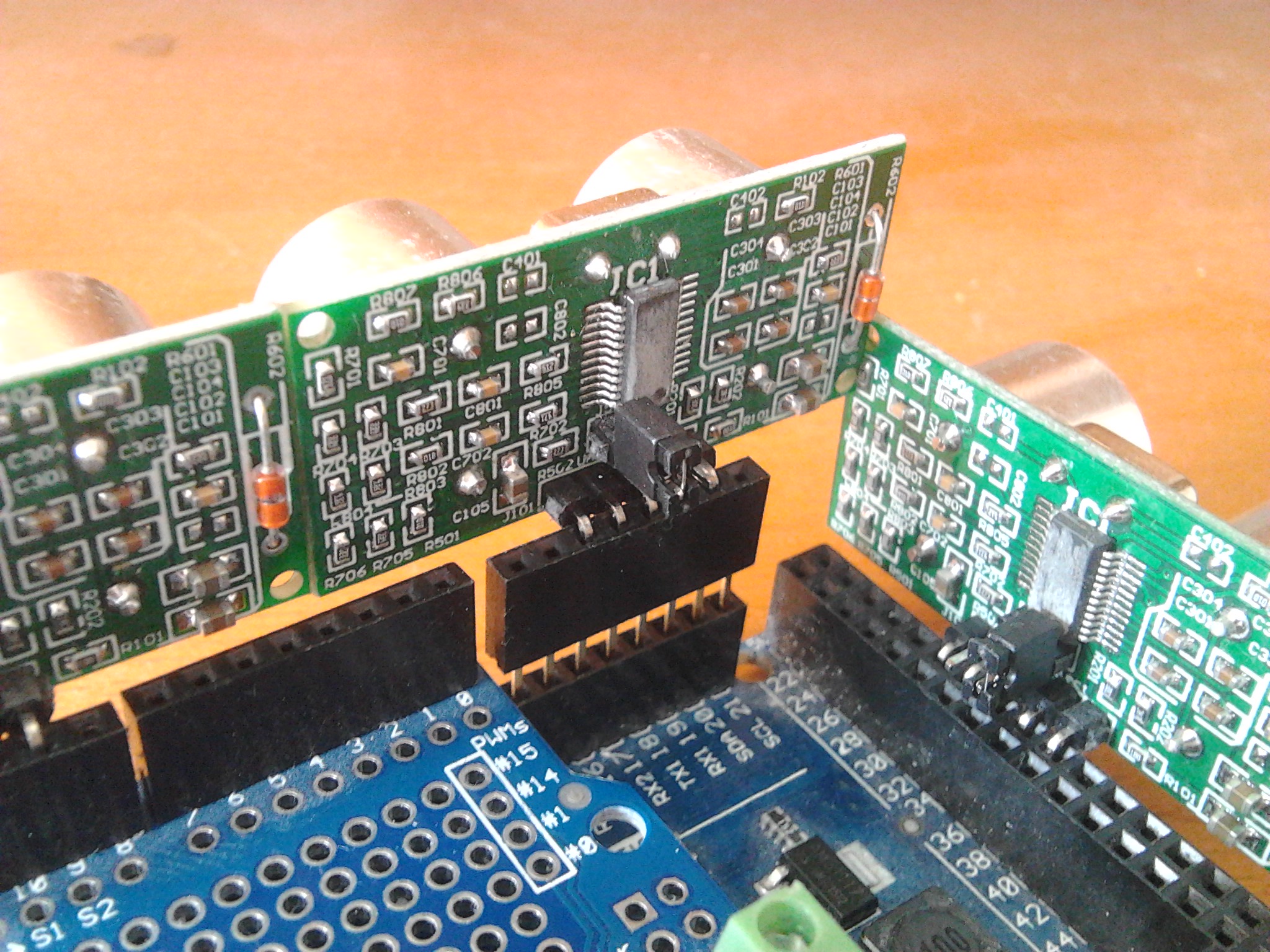
Because HC-SR04 ultrasonic ranging modules typically need to look sideways, you can buy mounting brackets for them For just testing I wanted to directly use Arduino Uno pins instead, see photo below. So I had to define VCC0/1 and GND0/1, configure all as OUTPUT and set them to HIGH/LOW. Uno spec says that digital pins can deliver 20mA, HC-SR04 spec says it draws 2mA. So for me that sounds safe to do. Is it safe? Are there reasons for not doing so?

This is sample sketch:

#define VCC0 2
#define trigPin0 3
#define echoPin0 4
#define GND0 5

#define VCC1 A0
#define trigPin1 A1
#define echoPin1 A2
#define GND1 A3

void setup() {
  Serial.begin (9600);
  pinMode(VCC0, OUTPUT);  digitalWrite(VCC0, HIGH);
  pinMode(trigPin0, OUTPUT);
  pinMode(echoPin0, INPUT);
  pinMode(GND0, OUTPUT);  digitalWrite(GND0, LOW);

  pinMode(VCC1, OUTPUT);  digitalWrite(VCC1, HIGH);
  pinMode(trigPin1, OUTPUT);
  pinMode(echoPin1, INPUT);
  pinMode(GND1, OUTPUT);  digitalWrite(GND1, LOW);
}

void loop() {
  long duration, distance;
  distance = distdur(trigPin0, echoPin0, duration);
  out(distance, duration);
  distance = distdur(trigPin1, echoPin1, duration);
  out(distance, duration);
  Serial.println();
}

void out(long distance, long duration) {
  Serial.print(distance);
  Serial.print(" cm (");
  Serial.print(duration);
  Serial.print(")  ");
}

long distdur(int trigPin, int echoPin, long &duration) {
  long distance;
  digitalWrite(trigPin, LOW);
  delayMicroseconds(2);
  digitalWrite(trigPin, HIGH);
  delayMicroseconds(10);
  digitalWrite(trigPin, LOW);
  duration = pulseIn(echoPin, HIGH);
  distance = (duration/2) / 29.1;
  return (distance>400) ? 400 : distance;
}

This is the output generated:

8 cm (497)  27 cm (1610)  
8 cm (503)  57 cm (3347)  
8 cm (496)  25 cm (1465)  
8 cm (503)  23 cm (1348)  
8 cm (497)  20 cm (1216)  
8 cm (503)  19 cm (1153)  
8 cm (499)  58 cm (3409)  
8 cm (496)  58 cm (3418)  
8 cm (503)  57 cm (3371)  
8 cm (497)  20 cm (1169)  
8 cm (503)  19 cm (1156)  
8 cm (497)  20 cm (1165)

Hermann.

Are there reasons for not doing so?

Yes, it is a waste of pins!

It should work, though. Be careful with the code. If you set the pins connected to Vcc & gnd on the sensor to the wrong values, you could damage the sensor or the Arduino.

PaulRB:
Yes, it is a waste of pins!

I agree with you in general, for real applications.

But for development/testing above method is fine for me since you confirmed it is OK (if not incorrectly feeding VCCx/GNDy pins).

Away from home I have only my 5$ 24MHz logic analyzer with me, but that is more than adequate for dealing with ultrasonic signals.

My application will be that both sensors will have a short distance to obstacle as shown in photo below.
I am really impressed that two short distance sensor measurements (4cm/7cm) take only 4.423ms including Serial output.
After commenting out all Serial output statements, two measurements in above sketch take only 1.807ms in total:

This is for driving an autonomous robot quickly parallel to a long straight wall at constant distance. Even if the robot will ever achieve 10m/s(36km/h) that means that every 1000/500=2cm both measurements will be available for PID controller [I do not expect the robot to go over 5m/s linear speed (radially it did show 18m/s or 64km/h)].

Hermann.

This method also works with "wrong voltage" sensors, like 5V HC-SR04 ultrasonic range sensor and 3.3V Arduino Due, although some changes are needed. First, the "Echo" pin 5V have to be scaled down to 3.3V before sent to a Due pin. And HC-SR04 VCC pin needs to get 5V.

I revived one of my Arduebots for getting linear speed measurements by driving parallel to a long straight wall as described in previous posting.

I had to remove the top of Mega acryllic box in order to fit the first HC-SR04 ultrasonic sensor into SCL 21 and 5V pins. The second sensor gets placed "naturally" into pins GND/13/12/11 of v2.0 motor shield.

This is full view, with logic level converter on the right (click images for details):

Trig pin of HC-SR04 is connected to a female connector coming from bottom through Due board mounting hole between SCL and 5V. The corresponding mounting hole at Mega box bottom was too small, but the acrylic could be easily removed with a screw driver:

For the second HC-SR04 sensor Echo pin has to be bended in order to go into logic level converter. VCC pin has to be bended as well in order to get 5V:

Both work fine, this is Serial output of below sketch with sensors orthogonal to a wooden wall:

...
349 mm (2032)  349 mm (2036)  
349 mm (2032)  350 mm (2038)  
349 mm (2032)  349 mm (2037)  
349 mm (2033)  349 mm (2037)  
349 mm (2032)  349 mm (2036)  
349 mm (2032)  349 mm (2037)  
348 mm (2031)  349 mm (2036)  
349 mm (2032)  349 mm (2036)  
...

And this is the simple sketch (SCL is D21):

// for Due with Echo voltage down
//#define VCC0 2      // 5V
#define trigPin0 2
#define echoPin0 3
#define GND0 21

#define VCC1 11     
#define trigPin1 12
#define echoPin1 7
//#define GND1 4     // GND

void setup() {
  Serial.begin (57600);

//  pinMode(VCC0, OUTPUT);  digitalWrite(VCC0, HIGH);
  pinMode(trigPin0, OUTPUT);
  pinMode(echoPin0, INPUT);
  pinMode(GND0, OUTPUT);  digitalWrite(GND0, LOW);

//  pinMode(VCC1, OUTPUT);  digitalWrite(VCC1, HIGH);  // 3.3V
  pinMode(trigPin1, OUTPUT);
  pinMode(echoPin1, INPUT);
//  pinMode(GND1, OUTPUT);  digitalWrite(GND0, LOW);
}

// for 31cm --> 1.82ms / 272Hz
void loop() {
  long duration, distance;
  distance = distdur(trigPin0, echoPin0, duration);
  out(distance, duration);
  delay(3);
  distance = distdur(trigPin1, echoPin1, duration);
  out(distance, duration);
  Serial.println();
  delay(3);
}

void out(long distance, long duration) {
  Serial.print(distance);
  Serial.print(" mm (");
  Serial.print(duration);
  Serial.print(")  ");
}

long distdur(int trigPin, int echoPin, long &duration) {
  long distance;
  digitalWrite(trigPin, LOW);
  delayMicroseconds(2);
  digitalWrite(trigPin, HIGH);
  delayMicroseconds(10);
  digitalWrite(trigPin, LOW);
  duration = pulseIn(echoPin, HIGH);
  distance = (duration/2) / 2.91;
  return (distance>4000) ? 4000 : distance;
}

Hermann.

P.S:
I ordered some US-100 ultrasonic range sensors because they can work with 3.3V as well as 5V. A little more expensive than HC-SR04 sensors, but allow for directly plug into Arduino Due pins without pin bending by the method described in initial posting of this thread.

P.P.S:
I have read some comparisons on HC-SR04 and US-100. I cannot confirm unprecise readings mentioned in those comparisons, at least the HC-SR04 sensors I have give precise readings (the ms values in parenthesis above).

This is followup on "P.S." from previous posting.

Today I received the first pair of US-100 ultrasonic distance sensors.
I just tested them, this time just "as is" with no pin bending needed since US-100 does work with Due 3.3V (2.4V-5.5V).
Here even more "waste" of Due pins, since US-100 has 5 instead of 4 pins (two GND pins).
You can click on photo for the details:

Unlike the HC-SR04 the US-100 has two different distance measurement modes.
I did not test the serial mode yet (distance in millimeter or temperature gets returned in two bytes).
I removed the shunt from the mode selection jumper and used pulse width mode.
Below is the modified sketch, the distance formula is different,

Hermann.

// for Due
#define VCC0 21      // 3.3V
#define trigPin0 20
#define echoPin0 19
#define GND0a 18
#define GND0b 17

#define VCC1 9     
#define trigPin1 10
#define echoPin1 11
#define GND1a 12
#define GND1b 12

void setup() {
  Serial.begin (57600);

  pinMode(VCC0, OUTPUT);  digitalWrite(VCC0, HIGH);
  pinMode(trigPin0, OUTPUT);
  pinMode(echoPin0, INPUT);
  pinMode(GND0a, OUTPUT);  digitalWrite(GND0a, LOW);
  pinMode(GND0b, OUTPUT);  digitalWrite(GND0b, LOW);

  pinMode(VCC1, OUTPUT);  digitalWrite(VCC1, HIGH);  // 3.3V
  pinMode(trigPin1, OUTPUT);
  pinMode(echoPin1, INPUT);
  pinMode(GND1a, OUTPUT);  digitalWrite(GND1a, LOW);
  pinMode(GND1b, OUTPUT);  digitalWrite(GND1b, LOW);
}

void loop() {
  long duration, distance;
  distance = distdur(trigPin0, echoPin0, duration);
  out(distance, duration);
  delay(3);
  distance = distdur(trigPin1, echoPin1, duration);
  out(distance, duration);
  Serial.println();
  delay(3);
}

void out(long distance, long duration) {
  Serial.print(distance);
  Serial.print(" mm (");
  Serial.print(duration);
  Serial.print(")  ");
}

long distdur(int trigPin, int echoPin, long &duration) {
  long distance;
  digitalWrite(trigPin, LOW);
  delayMicroseconds(2);
  digitalWrite(trigPin, HIGH);
  delayMicroseconds(10);
  digitalWrite(trigPin, LOW);
  duration = pulseIn(echoPin, HIGH);
  distance = duration * 34 / 100 / 2;
  return (distance>4000) ? 4000 : distance;
}

After I made some progress with new caterpillar robot platform, and that platform turned out to be quite robust, I plan to start my "drive quickly parallel to a long wall" experiments on that platform. What worked there was an Arduino Uno with motor shield v2 (the 1.2A per motor were good enough).

The only change I will do is to replace the Uno by Arduino Due. So I played a bit with 3 of my 4 US-100 ultrasonic range sensors. For quickly moving I wanted to increase stability. For that I added a 8 pin 10mm female header in order to get D14-D21 onto same height as D0-D13. And instead of D17-D21 I used D16-D20 for 2nd US-100 sensor. This made distance between both sideward US-100s very small, so that I was able to superglue them together. The third US-100 looks forward in order to allow for some automated robot stop at some placed obstacle (click for details):

Yes, the third US-100 wates even more pins, but the Due has more than 50 ...

Hermann.

P.S:
I moved the forward looking US-100 slightly to the right. In that position its top half right touches the front sideward US-100 bottom half. Then I superglued those two together as well. Now the whole construction is really stiff.

P.P.S:
All three sensors work fine

...
258 mm (1519)  250 mm (1475)  198 mm (1168)  
258 mm (1520)  250 mm (1475)  198 mm (1168)  
258 mm (1519)  250 mm (1475)  198 mm (1168)  
262 mm (1542)  250 mm (1475)  198 mm (1168)  
...

with this sketch:

// for Due
#define VCC0 20      // 3.3V
#define trigPin0 19
#define echoPin0 18
#define GND0a 17
#define GND0b 16

#define VCC1 9     
#define trigPin1 10
#define echoPin1 11
#define GND1a 12
#define GND1b 13

#define VCC2 39     
#define trigPin2 37
#define echoPin2 35
#define GND2a 33
#define GND2b 31

void setup() {
  Serial.begin (57600);

  pinMode(VCC0, OUTPUT);  digitalWrite(VCC0, HIGH);
  pinMode(trigPin0, OUTPUT);
  pinMode(echoPin0, INPUT);
  pinMode(GND0a, OUTPUT);  digitalWrite(GND0a, LOW);
  pinMode(GND0b, OUTPUT);  digitalWrite(GND0b, LOW);

  pinMode(VCC1, OUTPUT);  digitalWrite(VCC1, HIGH);  // 3.3V
  pinMode(trigPin1, OUTPUT);
  pinMode(echoPin1, INPUT);
  pinMode(GND1a, OUTPUT);  digitalWrite(GND1a, LOW);
  pinMode(GND1b, OUTPUT);  digitalWrite(GND1b, LOW);

  pinMode(VCC2, OUTPUT);  digitalWrite(VCC2, HIGH);  // 3.3V
  pinMode(trigPin2, OUTPUT);
  pinMode(echoPin2, INPUT);
  pinMode(GND2a, OUTPUT);  digitalWrite(GND2a, LOW);
  pinMode(GND2b, OUTPUT);  digitalWrite(GND2b, LOW);
}

void loop() {
  long duration, distance;
  distance = distdur(trigPin0, echoPin0, duration);
  out(distance, duration);
  delay(3);
  distance = distdur(trigPin1, echoPin1, duration);
  out(distance, duration);
  delay(3);
  distance = distdur(trigPin2, echoPin2, duration);
  out(distance, duration);
  Serial.println();
  delay(3);
}

void out(long distance, long duration) {
  Serial.print(distance);
  Serial.print(" mm (");
  Serial.print(duration);
  Serial.print(")  ");
}

long distdur(int trigPin, int echoPin, long &duration) {
  long distance;
  digitalWrite(trigPin, LOW);
  delayMicroseconds(2);
  digitalWrite(trigPin, HIGH);
//  delayMicroseconds(10);
  delayMicroseconds(50);
  digitalWrite(trigPin, LOW);
  duration = pulseIn(echoPin, HIGH);
  distance = duration * 34 / 100 / 2;
  return (distance>4000) ? 4000 : distance;
}

P.P.P.S:
superglued sensors are really stiff, and actual sensor measurements are good: