Hello.
I have three microcontrollers: 2 attiny85 and atmega328p.
The 2 attiny85 will serve a simple logic and output a signal of HIGH logic level for 50 milliseconds on PB1 pin.
The atmega328p is the receiver of the signal. It receives the signal on an input pin PC0. It doesn't care who sent the signal. I want it to use only one pin to receive the signal instead of dedicating a pin for each sender. It will also allow me to easily add a new sender of the signal (maybe also a button) without changing software and dedicating new pins.
The only question I have: Is if safe to design the circuit so that output pins are connected together to an input pin of another microcontroller? In what case it will cause a damage to any of the microcontrollers in the circuit?
How to design a safe circuit but still using only one receiving pin, if possible?
But it can be done with a bit more hardware. You need a transistor per signal, wired in parallel, with each base driven by one output. It's called a wired OR circuit.
Or, use Larry's approach, just a bit more modern, using FETs instead of transistors. Same difference, really.
Hi, @user749887
Do you have enough inputs on the 328 to have an input for each of the THREE sources and deal with them in software?
What else will the 328 have as inputs?
Works, could do on the '328 too, but the button is a killer. But the OP asked specifically about outputs.
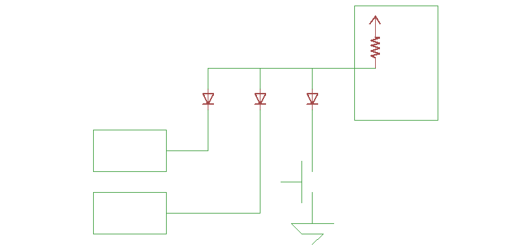
Diode OR works, as long as the input thresholds are ok; back to the days of DTL, eh?
And if you switch to the pullup case, you can probably use the internal pullup. Saves yet another component, so all you need is a diode per signal to be OR'd.