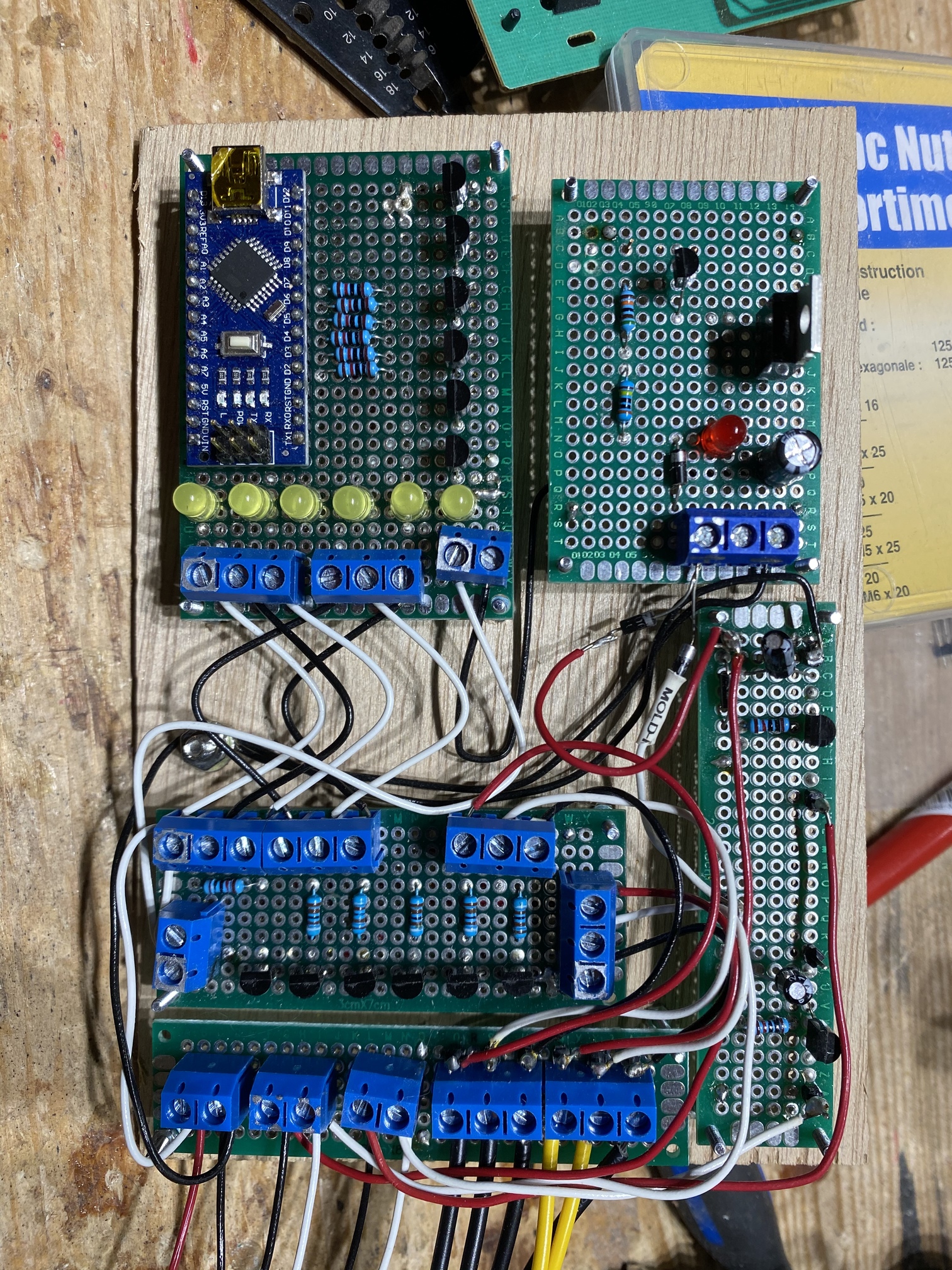
Latley I have burned out 2 nano boards. Both were loaded with a simple 10 channel 5mm led flashing sequence program (560 ohm resistors for each). Powered by a small 5aH 12v battery . They both seemed to just die all of a sudden. The one that died today had the pwr, tx and rx light on steady and reset did nothing , the AT chip was super hot. It had been working flawlessly as a cool power indicator for months.
I've heard mixed info on power input for nano's. Some say 5-16 volts is no problem, others say never go over 5v regardless of the spec sheet. I'm going to start adding an L7805 regulator to every one from now on but was it the 12 volts causing the premature death on these boards or what?
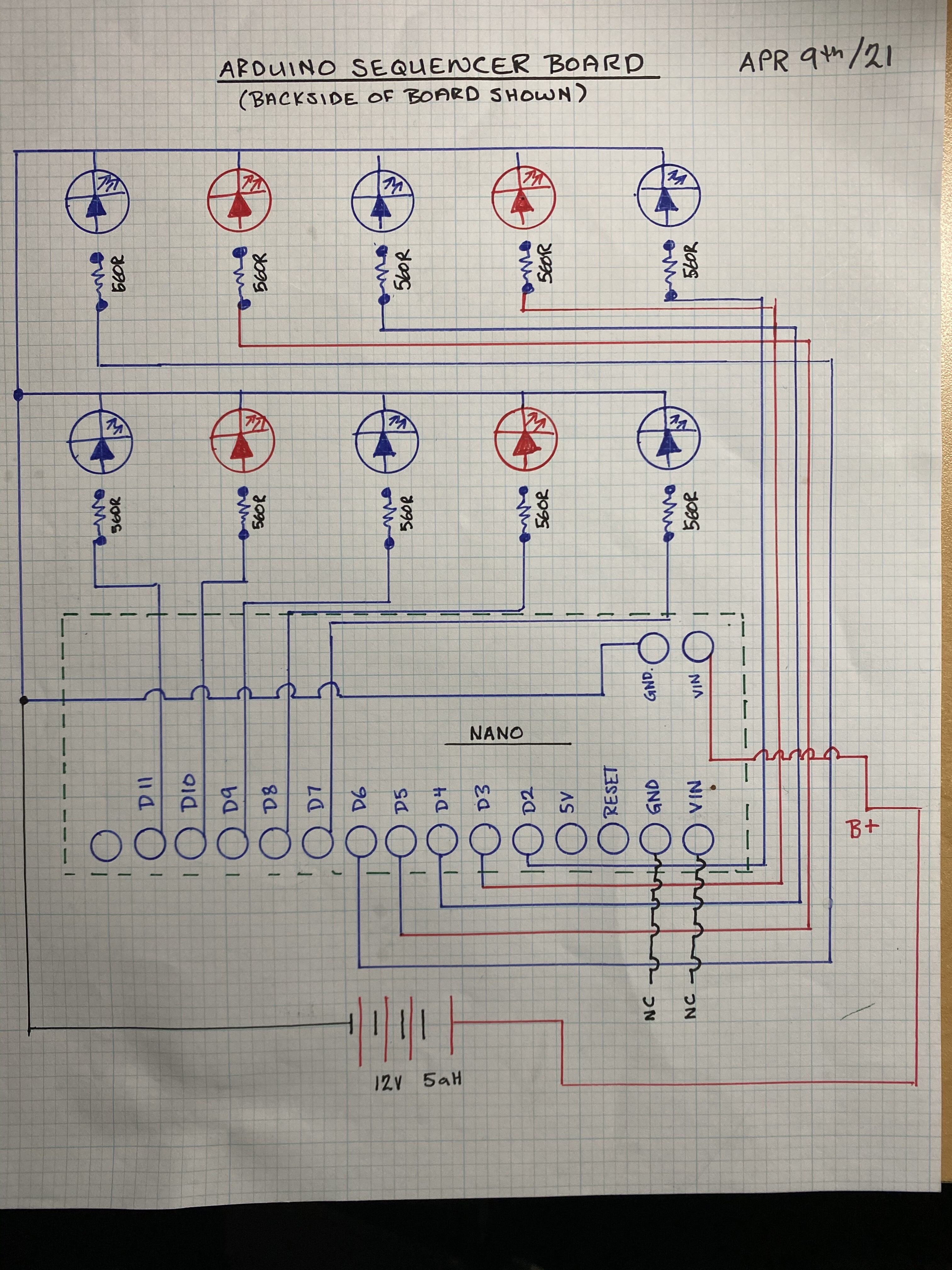
How many leds are there ? 10 leds ?
Let's say 6 mA per led, that is a total of 60 mA (or is only one led turned on at a time ?). I guess 30mA for the Nano. Total of 630 mW that the voltage regulator has to dissipate.
The voltage regulator is just a small one. At 12V it can barely give enough current for the Nano itself.
I would set the limit to about 100 or 200 mW for that small voltage regulator.
Is it a cheap clone ? Perhaps they used a 5V capacitor for the 12V side. Perhaps they put a clone of the voltage regulator on the board. Perhaps they omitted decoupling capacitors causing a lot of noise which draws more power. Perhaps ... well, you get the idea.
Yes. Nano itself is fine on 12V. The problem usually comes with the other components you attach to the nano, expecting it's regulator to power them also.
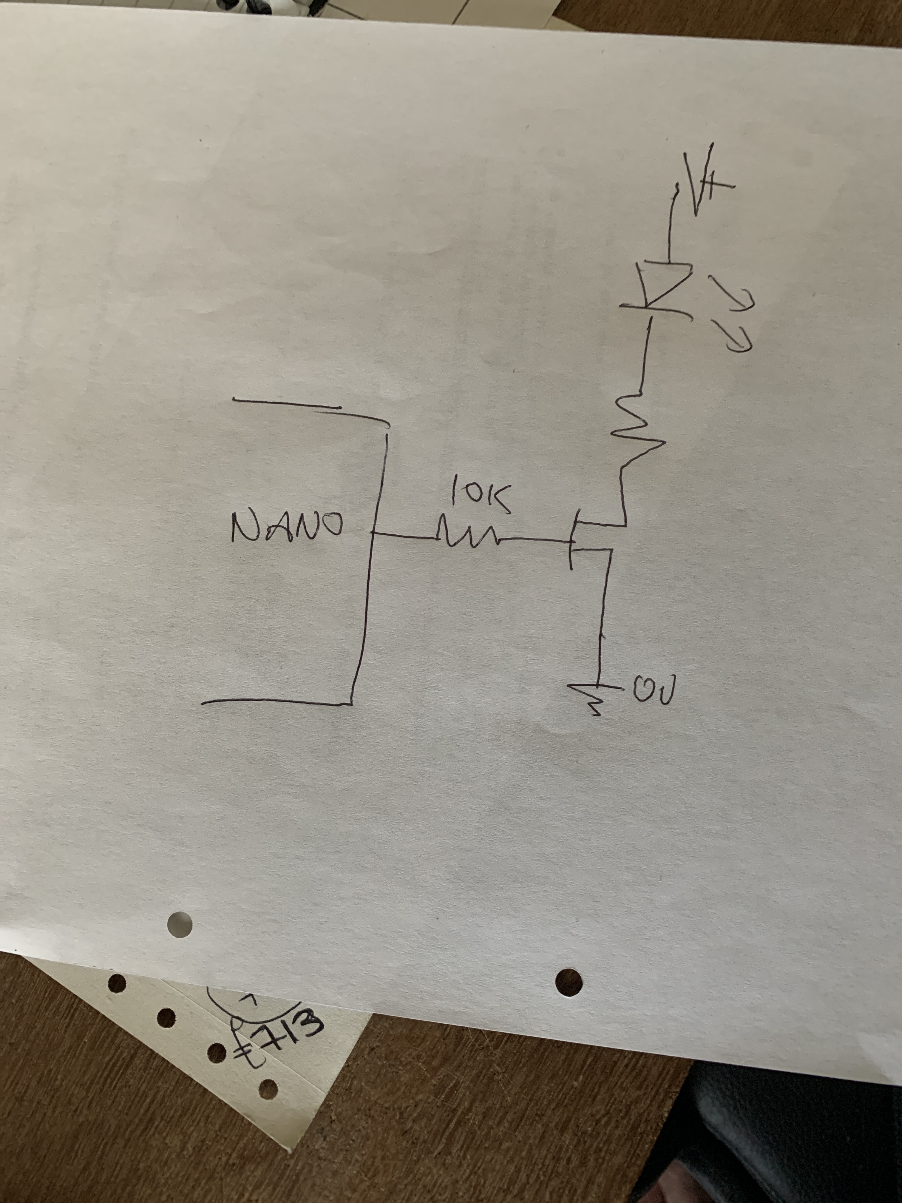
Then perhaps you are drawing/sinking too much current from the AVR chip, and adding extra regulators will not help that. Post your schematic please.
Which may also overheat. Suggest you use 12V-5V DC-DC ("buck") converter instead.
I have run Nano’s off 12v , actually rising to 13.2 sometimes ( lead acid battery ) without any issues .
I have a Nano running off a 12v lead acid that has run for 3-4 years continually .
The problem as mentioned is heat dissipation .
Driving any significant load at high Vin is asking for trouble especially as clones often use tiny regulators too .
The specs for official Nanos can’t be assumed correct for cheap clones either .
You shouldn’t use the processor to power large loads either , at any input voltage ( see data sheet on the 328)
So Hammy, not understanding your response completely. Are you saying driving 10 5mm leds in a flashing sequencing pattern is overloading the board??? If so , could you recommend the correct way to run the leds if it isnt straight off the pins?
Thanks hammy, I have a bit of experience driving larger automotive led lights with transistors with this same set up. Just never assumed 10 little 5mm leds on separate pins would ever come close to overloading the nano board. Will rework mine circuit like u advise and see how things work out. All in all it has to be much easier on the board, thanks
With 560R series resistors, those LEDs will be drawing < 6mA each for red and < 4mA for blue, in total < 50mA will all LEDs on. The Nano itself will draw ~30mA, so around 80mA in total. The regulator will need to dissipate 80*(12-5) = 560mW. I would expect it to get a little warm, but I'm surprised that they are failing, especially if all 10 LEDs are on together only for short periods.
I suspect there is another issue here, perhaps a short circuit caused by a spot of careless soldering or something.
What is the current draw of the circuit from the battery? If it's more than around that 80mA, that could indicate a short somewhere.