I purchased my Nano a few months ago from Arduino, so it's not a clone. I have it on my breadboard, and I was working on a project and testing some voltages, and all of a sudden all of the LED's on the Nano board flashed, and now nothing happens. It was powered by a 9V power supply at the VIN post. I removed it from the board and connected the power directly to the VIN and no response, and also no response from USB power source.
So is it toast, or is there a way to fix it? Thanks.
Sounds like toast, unfortunately. I NEVER use VIN when developing, sometimes not even for production, I prefer 12V to BUCK to LDR to USB 5V, but then I am old fashioned and don't like to put voltages on naked pins if there is another way.
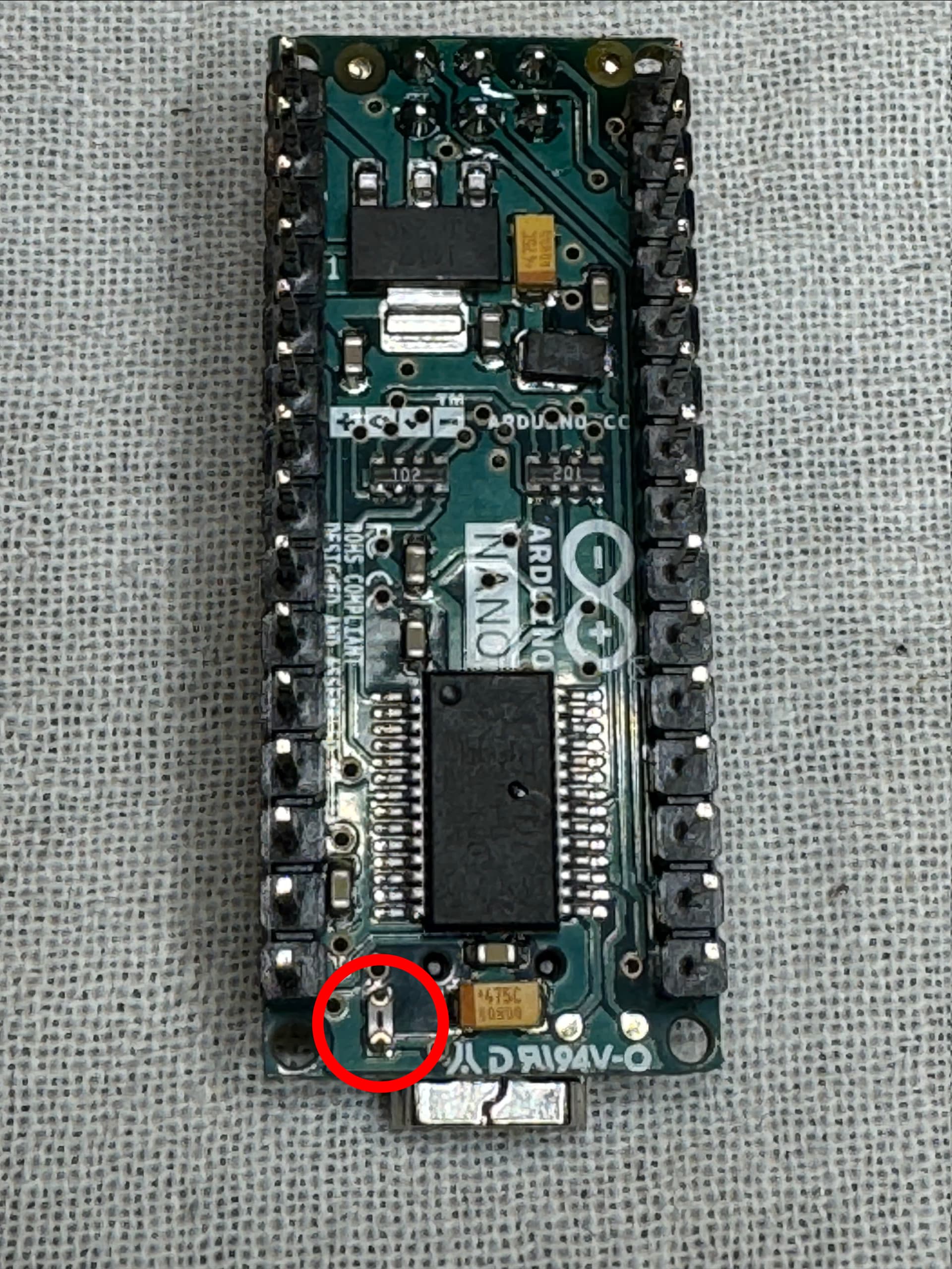
Attached are images of both sides of the Nano.
It was not also powered at the USB.
I put a meter across the diode and its Open, so it must be blown.
Also, I checked continuity between the GND pin on one side of the board, and the GND, VIN and 5V pins on the other side. There is continuity between all of them. Sounds to me like a short.
I just checked the continuity among all the pins on the LM11171MPX Linear Voltage Regulator, and there is continuity among all of them.
Does it sound like this is blown, and is the bad part? Would that be the reason that there's no power to the circuit whether the power source is USB or VIN?
Can't see how the diode would have burned out if it was powered by Vin.
The diode does nothing while powered by Vin so it should not matter if it's shorted or open. However, don't connect anything to the USB with something also connected to Vin.
I had just checked that an NOTHING on 5V pin. While connected I heard a faint "click" sound, and then smelled "burning". So something went up in "flames". I'll just order a new NANO. I doubt this is a warranty issue.
I'm trying to pursue fixing the board, or trashing it if it can't be repaired.
I think I shorted the board when I was powering it from the VIN. I think I hooked up the input voltage to an output voltage pin. Anyway, the help I got from members was that I probably needed to replace the Voltage regulator and maybe the diode.
So I got a new SMD Voltage Regulator and installed that yesterday. But still no response from Nano. I'm using the USB input for 5V supply. I tested the voltage at the USB, and I've got 5V on its power pin. However I don't have any voltage at either of the 5 V pins. Also, I don't have any voltage on either side of the diode. I used my DMM in Diode mode to check health of the diode, and I believe it is functioning properly.
So my guess is that if I improperly injected voltage at an Output voltage jack, I might have fried some other component. Like maybe the main IC.
Can anyone suggest how I can track down the problem?
I tested the existing diode near the voltage regulator, and it tests fine. One connection reads OL, and the other reads 0.175v using the diode tester on my multimeter. So I think the voltage regulator is good because it's new, and the diode tests ok. As to the fuse, where is it located? Check out the photos shown in the link in post #2 above. Thanks.
I was thinking it was the "fuse" that looks the same as the one you ID'd, but up at the other end of the board, and above and to the right side of the diode, which is the "large" black rectangle component below the tan component which is off the right side of the voltage regulator.