I'm looking to build a demonstration/teaching project, and it would require ~10 soldered prototype shields all stacked together. It seems an easy way to create a vertical power/signal bus. I would have power, digital and analogue (50mV) signals. And Ethernet. I can order the weakest signal /fastest shields closest to the Uno.
I've searched this forum, and the Q&As seem to revolve around pin assignments. That's not a problem for me. I'm interested in whether this is reliable over a period of couple/three years. Connector oxidisation, contact resistance, physical stability, etc. The construction would be encased and indoors, and the stack would be laterally braced.
Any views please?
Most shields (Ethernet is a good example) don't have sufficient clearance to add additional shields above them. The pin pass throughs are only good to stick pins or wires into.
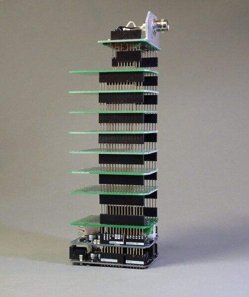
Err, mine do. They have long pins and clear the Ethernet socket by 1.5mm. Overall separation between PCBs is ~ 15mm.
Since OP is working with proto shields, he just needs to ascertain the pin length and the power is up to scratch. My proto shields have 3/4" storey to storey height. Other than the Ethernet socket, the only item I know of that actually needs long pins to clear it is the DS3231 module. I would be surprised if weak signals are a problem for this exercise, same applies to "fast shields."
Thanks. Re. power; yes. One of the shields will be a heat sinked 1A LM7805 that will upgrade the onboard Uno SMD regulator, which will be removed.
PS. You can always notch the proto boards to clear obstacles from beneath.
To answer the original question, using the stacking pins for more than 1 or 2 shields would increase your signal integrity issues exponentially.
Some of my projects use a custom main board with the extra functionality, and plug the Arduino in as a daughterboard. In one case, there’s an extra header for a second shield to plug in as well.
cossoft:
Thanks. Re. power; yes. One of the shields will be a heat sinked 1A LM7805 that will upgrade the onboard Uno SMD regulator, which will be removed
Having a decent power supply as a shield is a good idea. There is no need to remove the original Uno regulator to your possible later regret, it can be simply left as redundant. Note that some shields have their own regulators and/or provisions for separate power.
PS. You can always notch the proto boards to clear obstacles from beneath.
I can't imagine that ever being necessary, but cutting to length is legit, particulaly if you are stacking on a Mega. There is a short board available that will clear an Ethernet socket with short pins. I have two, I don't think they are such a good idea, but I didn't know any better when I bought them. Note particularly that not all proto boards have holes that align with the ICSP cluster. Freetronics are/were guilty of this, and for no good reason. Those pins are on the standard 0.1" grid.
I'm actually using boards similar to :-
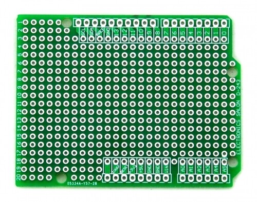
so there's no ICSP. They're bare.
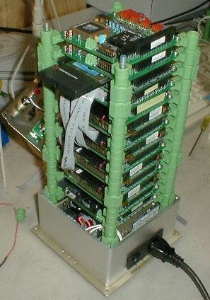
Pins are 2.54mm apart, and slow. Only the Ethernet is fast and that speed only travels from the Uno to the Ethernet shield (directly above it). NeoPixels are fast too but good out to >1000mm. I got my inspiration from PC/104 architecture than runs in the many MHz. These stack quite high:-
The on-board regulator has been removed as I also want a 12V rail in the bus. That's passing via the Vin pin, and I don't want 5V regulator contention.
I have 10 shields stacked in front of me, and other than being wobbly (not yet soldered), seem okayish. The highest pin resistance I can measure (relatively) from top to bottom is 0.2 Ohms. Dare I suggest it's sounding good : ?
?
That stacking kit you’re using looks good... even impressive !
‘okayish’ isn’t a word I like to use when building permanent projects, but what you have is probably as good as it gets for a lash-up !
As you note, having the fastest boards closest to the Arduino ‘might’ help, but the busses aren’t balanced or terminated, so any noise, ringing or capacitance as the lines get longer, are going to be there regardless.
What are you building ?
cossoft:
I'm actually using boards similar to :- so there's no ICSP. They're bare.
What I said was sometimes the holes don't align with the ICSP cluster. In your case, they do, thereby allowing you to use the cluster in the normal manner - if you need to. The problem is not the pin spacing, it is the alignment of the entire proto area relative to the headers. If the main patch looks kosher enough but is less than fourteen holes wide, it is time to get cautious.
lastchancename:
What are you building ?
My interest is in true random number generation for cryptography. I’m trying to demonstrate how easy it is to build entropy sources (the thingie that makes unpredictable noise). There are those who say that such is extremely difficult (like NIST/NSA/crypto.stackexchange.com). I vehemently disagree and am proving it.
The shield stack will be a collection of up to seven different types of entropy source. I can build each one at a time and stack them atop the Arduino & Ethernet shield to put them on-line. It’s going to be like an entropy source sampler:-
See REALLYREALLYRANDOM.com for some already on-line.