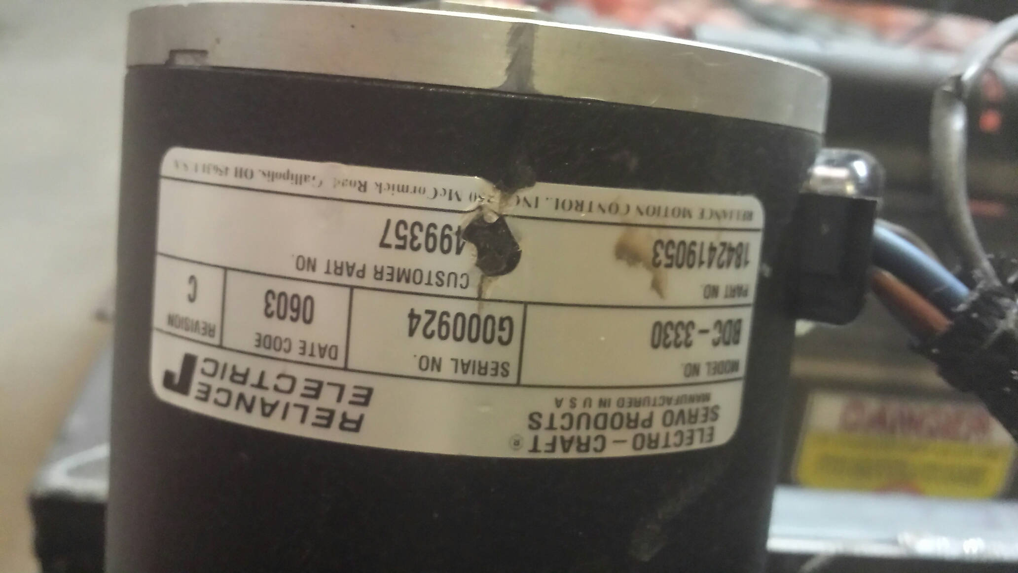
Is this a Servo or Brushed dc motor? It came off of a wheel chair. 4 wires to the motor. I know it says "servo products" on it but I'm not sure if it is.
The closest I've found is a forum. WheelchairDriver • View topic - ElectroCrafy model BDC3330... But I'm not sure that really answers one of my questions. Can I power that motor with a Sabertooth dual 25A motor driver? Or any other cheaper driver? I've used 2 wire dc wheelchair motors before but not with 4 wires.
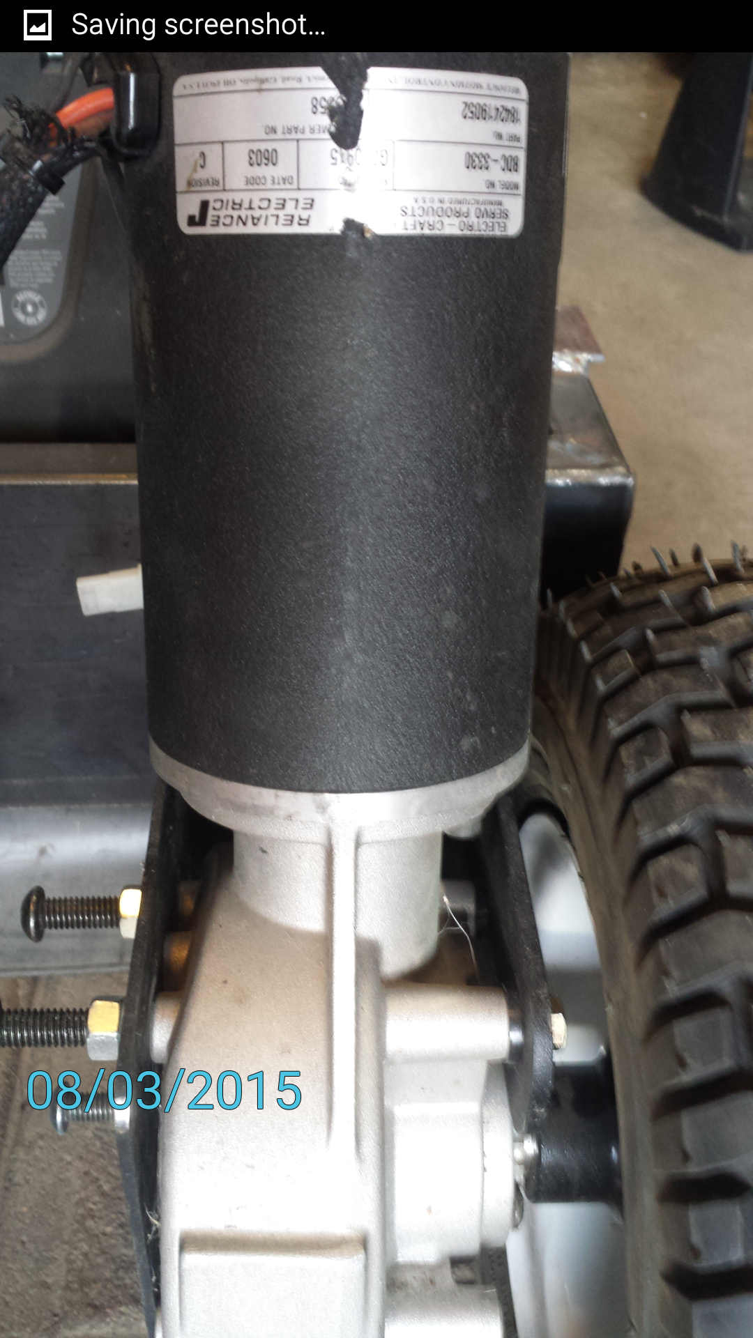
It would be nice if there were a picture of the entire motor from a couple of different angles - but in short, if you don't see and brush-cups (to allow replacement of brushes), then it is likely that these motors are brushless.
If that's the case, then I agree with SurferTim - an R/C ESC would be your best bet to control it - at least for the lowest cost (controllers for these large brushless motors exist - Roboteq is one source - but there are anything but inexpensive).
I'll try to get more pictures before tomorrow. I thought there would be a chance of it being a brushed motor because when I look at all of the brushless models they start with "BLDC - ...." mine is just BDC. So anyway I will get more pictures soon, and thanks you both for your input.
1.15Nm, 7500 rpm max (not the recommended operating speed, note, but the safety limit).
Depending on the windings (schemes A and B are listed) its aimed at 50V or 100V I think, and
looks quite capable of 500W or more.
So no its not brushed and needs a sensored BLDC motor driver and suitable high voltage
supply (depending on which winding version you have).
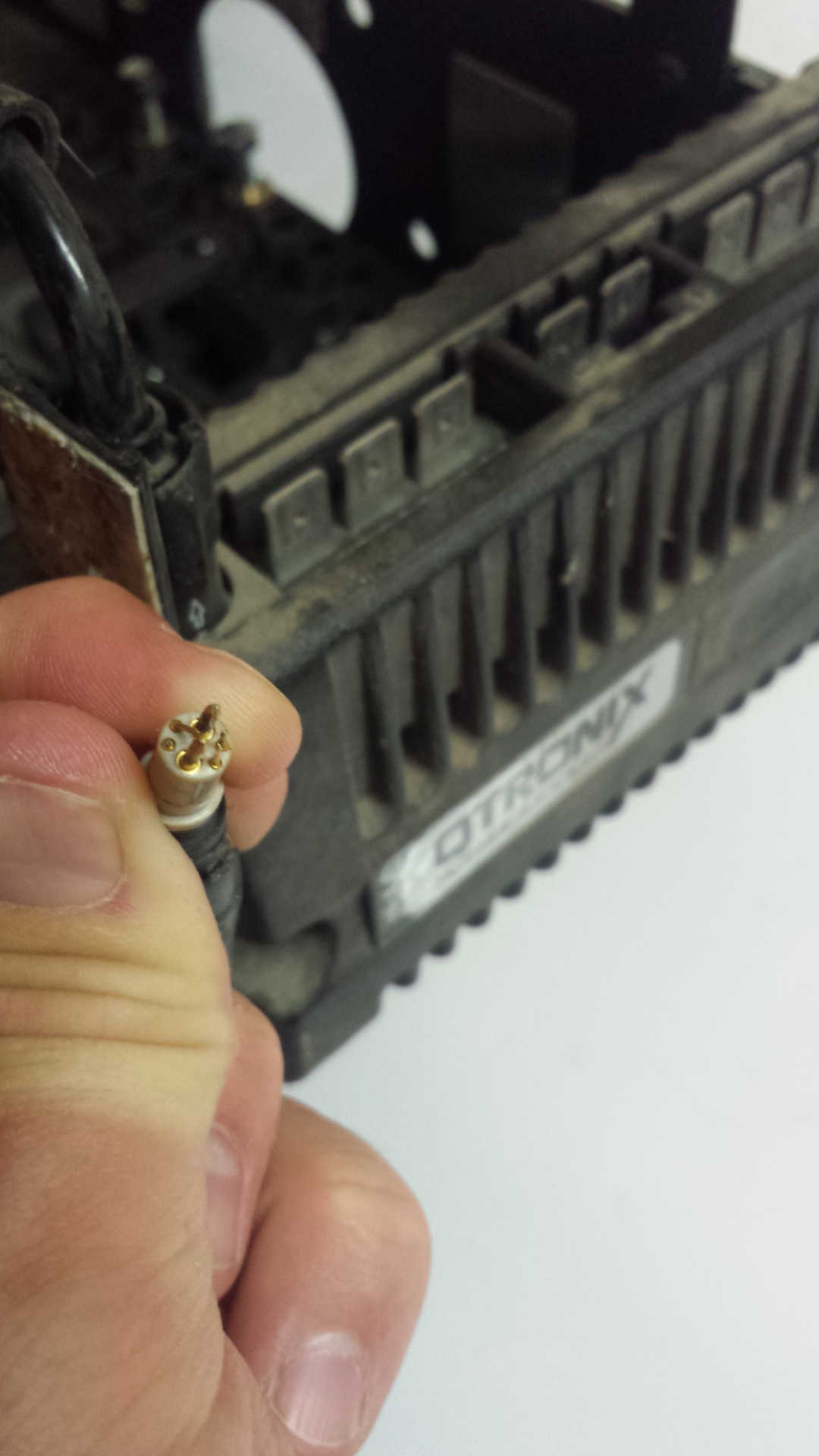
It has 8 wires, not 4, 3 phase wires and 5 for the hall sensors.
[ Actually thinking about it, its more likely this has custom windings for 24V, in which
case the phase-2-phase resistance ought to be well below 0.18 ohms.
Hey - good catch - and looking at that connector, it's pretty clear that the three lower pins are for the windings, and the other pins (only some, likely?) are for the sensors. The picture of the motor, though, only seems to show the wires for the windings - plus a (black?) wire going off in the distance (?).
We definitely need more and better pictures - but yeah, this is a brushless motor.
...and the controller for it won't be cheap. While you might be able to get it to work in open loop mode (big if) - it won't have much start-up torque.
Isaac96:
BDC should mean brushed, but that should not have 4 wires.
No, quite the contrary, DC is a brushed DC motor, B or BL means brushless. The DC
electric motor was around for 100 years before brushless motors came along, no-one
ever bothered calling them "brushed DC motors" till then because all DC motors always
had brushes.
PMDC = permanent magnet DC
BLDC = brushless (permanent magnet) DC
then you get series and shunt and various other field-winding based varieties,
typically at higher power and becoming obsolete (switched reluctance motors
may eventually win in the high power segment).
The motor has 8 wires as I said, 3 phases and a bundle of 5 wires for the hall sensors -
look at the connector.
Here are some more pictures. Just to make sure everyone thinks these are BLDC motors and I can get a consensus. If they are brushless I might have to get different motors.
Motor5.jpg shows what those extra wires went to I think. The bottom part of it Onegoes to a safety lock type mechanism that if the chair's frame isn't connected then the motors won't go (my guess). Connectors fit but not sure if that is truely where they go, I never had all the parts. So 2 wires to chair lock and 4 more wires directly to the motor. Some pictures show motors with brake cover on and some with brake cover off.
I also put a picture of the original controller and 6 wire joystick connector. Any ideas how hard it is to use the original controller with arduino?
BLDC as we said, no doubt. Have you measured the winding resistances yet?
Yes the extra end section with two wires is the brake, its a big solenoid that pushes against a spring
to release the shaft brake. Usually takes 0.5 to 1A at 24V, and you can just remove that section
if you aren't needing a safety brake.
MarkT:
BLDC as we said, no doubt. Have you measured the winding resistances yet?
I have not measured the winding resistance yet because even after googling a bit I'm not sure how to or what good it will do me. I would prefer not to open the motor up all the way if that is how it is done. I will read more on it and see if I can figure it out and do it this wkd.
I'm not sure how a resistance measurement is going to determine what voltage the motor is wound for unless we know one of the other variables in Ohm's Law. If we find the resistance, we would need the wattage or stall amp rating of the motor to determine the voltage rating. Is that not correct?