This is my first post and also new to Arduino world. I am thinking of using MEGA 2560 board as a prototype for my project that I currently do with binary ripple counters and multiplying DAC.
In board sense, wondering if I can use this board to act as an arbitrary waveform generator where the data pattern is uploaded at runtime as the user needs to and the board should output 14bit data pattern continuously with reference to an input clock (one data out per one clock input). The pattern should repeat itself as defined by the length of the pattern loaded. Whenever it starts to repeat the pattern it needs to output a signal (pulse or TTL) as well. The basic process is fixed, i.e. sending out a run time defined length of data pattern over the digital pins.
Is this something that can be done using this board? The important aspects here to consider is,
User should be able to update the pattern at runtime
The pattern wont be a fixed length and can vary depending on the user needs
Must output a signal for every repeat of the pattern
Able to update the pattern from PC side application (visual studio)
Yes, the idea is to output the 14bits on 14 different I/O pins which are then connected to a 14bit parallel DAC with the same clock feeding into the DAC as well. The clock range will be in the range of 15KHz -30KHz.
At 30Khz you would need to output two bytes on two I/O ports every 33 microsecs. That should be doable.
However a lot will depend on how much calculation is needed to figure what to output on the I/O ports. You have not described that part of the project.
I am also assuming that it will be OK for the output to pause while the user is providing new data.
There isn't much calculation here, very straight forward.
Here is how I imagine the workflow would be
Data pattern is generated on the PC application, the length of the data at max will be ~530 (12 or 14bit) data points
The above data is uploaded to MEGA flash (permitting on board storage which I think should be totally fine)
The only process that will be running continuously is to send out each data point (2 bytes) per clock input. For instance, incase of 530 data points, it should output a TTL signal for every 530 clocks and repeat from first data point.
Whenever the user wants to update data pattern, it will be generated on PC application and uploaded to the board (Ok for any delay it will have during this time)
This is all there is to it. Pretty simple actually.
530 unsigned integers is 1060 bytes. You might even be able to do it in RAM on an Arduino UNO. The 'clock' could be an external interrupt. The ISR would send out the next two bytes (you don't need to use all 16 bits), increment the counter, and turn on the "cycle" pin on roll-over.
Direct port manipulation would speed up the writes. The MEGA has plenty of 8-bit ports you could write. The UNO only has three ports (B, C, and D) and most of those have bits you should not touch.
kris123berkeley:
This is all there is to it. Pretty simple actually.
That sounds very straightforward.
I suggest you start thinking of the data being held as 16 bit values (you can easily treat the 2 (or 4) highest bits as 0) so that only 14 (or 12) bits have an effect. If you want to output a clock as well as the data you could use the high bit for the clock.
A Mega has the advantage that it has some I/O ports in which all 8 pins are available. Two of them will give you 16 bits. Using Port manipluation you can write the two I/O ports with two successive instructions 62.5 nanoseconds apart. I don't think there is any way to output more than 8 bits without that short gap.
Robin2:
Using Port manipluation you can write the two I/O ports with two successive instructions 62.5 nanoseconds apart. I don't think there is any way to output more than 8 bits without that short gap.
...R
This is a bit of info that I need to think about on how it effects the overall output waveform.
The only extra register I need to have access or update whenever the data pattern is updated is the one that holds the count value (10bit). The process uses this register value to cycle the loop continuously as long as the board is powered up. I am gonna go ahead and order this board and start playing with it.
thanks for all the info to both of you and I am sure will be back with more questions once I start playing with it.
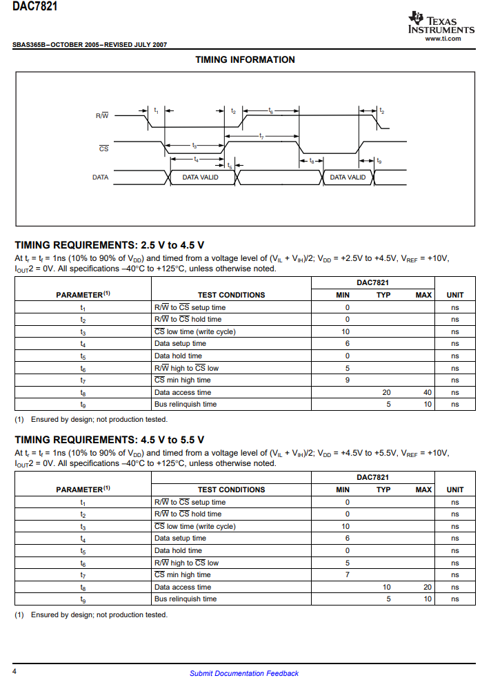
It just occurred to me that if your DAC only updates when it receives the CLK signal then the time gap between the outputs of the two bytes to make the full 16 bits will not be noticeable to the DAC as long as the CLK is part of the second byte to be written or is written separately after the two 8-bit values have been updated.
Yes, thats where I started looking into the timing diagrams of the DAC7821 which I plan to use. On pg:16 it says that the data is loaded into the input register when the clock (CS line) goes low and is latched to output DAC register when it goes high. In that case, I guess I should keep the clock low as long as the Mega is done outputting both bytes on the output lines and then pull clock to high just for long enough for 2 bytes to be written (as per the datasheet must be >=10ns). I can use the same clock input that I use with MEGA and delay it the amount of time (62.5ns as per your info + whatever time MEGA takes to latch out the data onto output lines) and then invert it for proper operation of DAC. At the moment my clock is 1us pulse.
One quick question, is it possible to use one of the PWM outputs of the MEGA to output a defined width pulse according to the input clock but delayed finite amount of time (basically the time it takes to write out 2bytes of data)?
kris123berkeley:
One quick question, is it possible to use one of the PWM outputs of the MEGA to output a defined width pulse according to the input clock but delayed finite amount of time (basically the time it takes to write out 2bytes of data)?
No need to do it in hardware. Just have the ISR send a clock pulse after it puts the data on the pins.
One hardware trick of the AVR chips: Write a 1 to any bit of the PINx register (Port input register) to toggle an output pin. Write the bit twice to send a short pulse.
Set CS HIGH to cause the data to be loaded into the DAC
I don't think the timing of any of these is critical as long as they are done in the correct order. The DAC can operate faster than the Arduino.
...R
I am thinking more like writing data to I/O ports before setting CS to low, that way data is available for DAC on its input lines to load into the input register as soon as the CS goes low and wait for like 20ns before switching CS to high.
But if it works in either case, thats good. Have to follow John's suggestion on toggling clock pulse output.
Ordered everything I needed for this today. Excited to try it out.
Just received the board and started playing with it by doing a simple step of recognizing the input clock and turning on/off on board led (while probing the pin output [pin 13] for that as well).
Using the online example for interrupt, I can successfully see it running, but there is too much delay and doesnt work all the time
void blink() {
state = !state;
digitalWrite(LED_BUILTIN, state);
}
Using actual clock (4us pulse at 15.45KHz), it is everywhere, most of the time it misses. When I change the duty cycle to 50% pulses, it works but there is a considerable amount of jitter and the lag is about 9us. If I move the digitalWrite command into loop section, the delay increases to about 15us.
Is there any other way to get this working at minimum delay and with 4us pulses? Is there some kind of clock frequency adjustments that can be updated to get the interrupt polling run faster?
Thanks for the tip. Port manipulation did improve a lot on the delay (~4us). But there is jitter in the output, sometimes it misses and the output phase inverts. Is there a way to make this more reliable. Before getting the rest of the logic going, I guess this should be straightened out for more stable output.
void blink() {
state = !state;
if (state)
PORTB = 0x32;
else
PORTB = 0x00;
}
In the attached video, you can see the jitter and phase change. Would like to see the output (CH2), close to identical to CH1 signal except for some fixed delay.