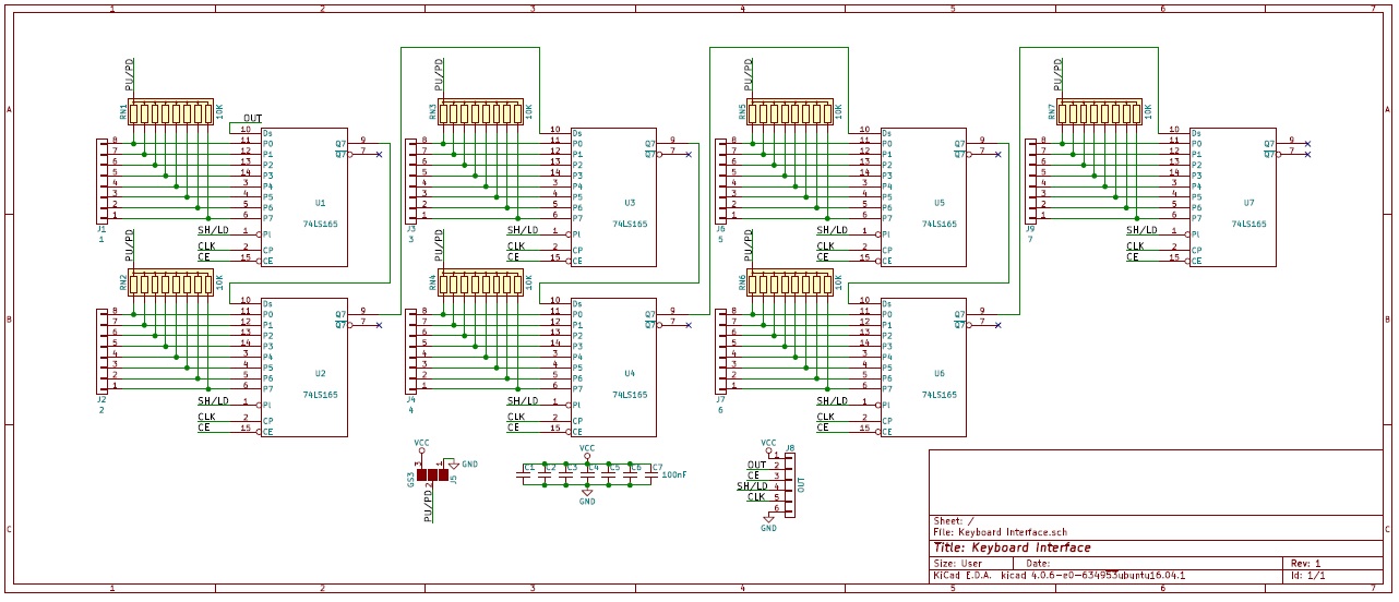
I am working on a digital keyboard, using shift registers to interface the 54 keys to an Arduino Due. Can somebody tell me if the attached schematic is correct?
The shift registers are (or at least should be) connected from U1 to U2, U2 to U3, etc.
Before somebody tells me that this is a clumsy way to do it, I am well aware of that.
The 74HC165s are incorrectly marked as 74LS165s. The CE (clock inhibit) pin is broken out in this schematic, but I fixed that already.
You can simplify your circuit, using 2 shift registers. One shifting out, and the other shifting in. Configure it in a 8 x 8 matrix. Shift a single bit out, 1 clock cycle. Then shift in, receive a bite. decode the keypress. Shift one clock cycle each time you receive a bite in.