Issue Powering HC-SR04 via Boost Converter

Hi I have been trying to solve this issue all night and finally figured I would see if any of you folk know what might be the issue. I am trying to build a battery powered data logger that uses the HC-SR04 ultrasonic sensor to measure the water level and then log it to an SD card.

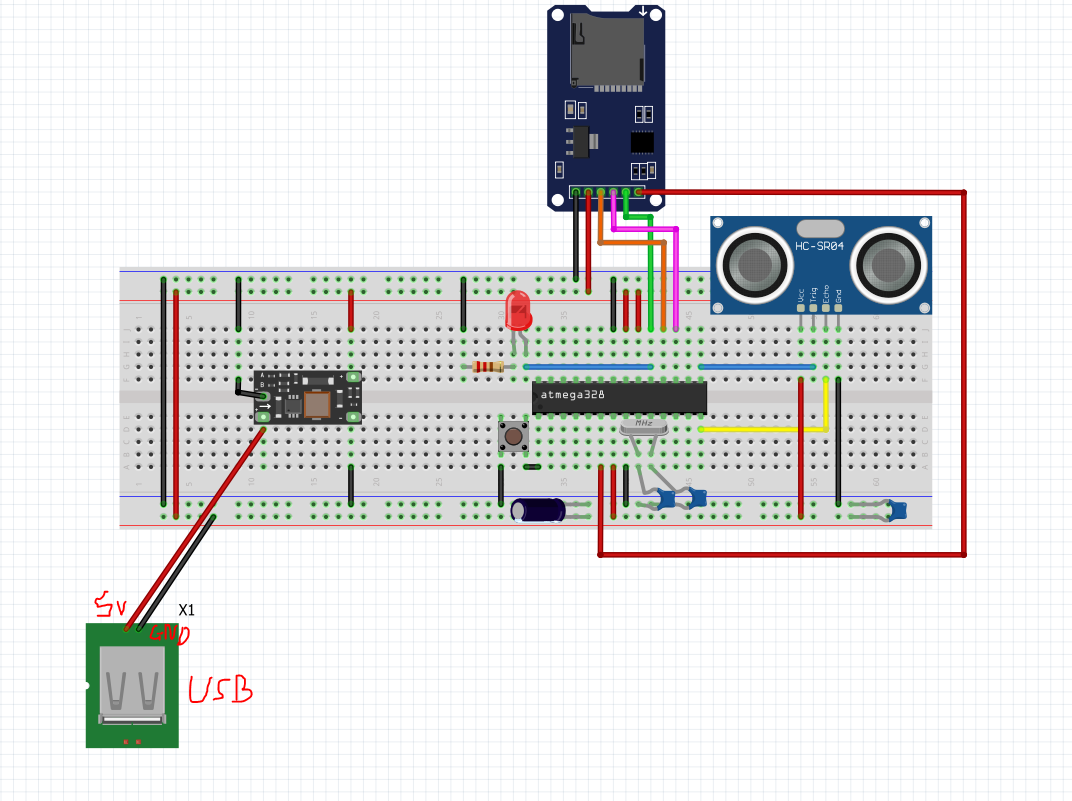
Having got the HC-SR04 measuring well and logging to the SD card connected to an Uno powered via USB from my laptop I migrated it all over on to a bare bones arduino on a breadboard which again worked as intended when the circuit was powered via the 5v and GND pins of the Uno board.

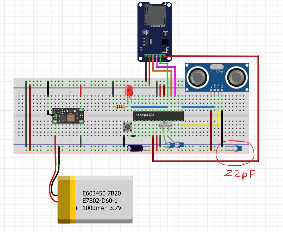
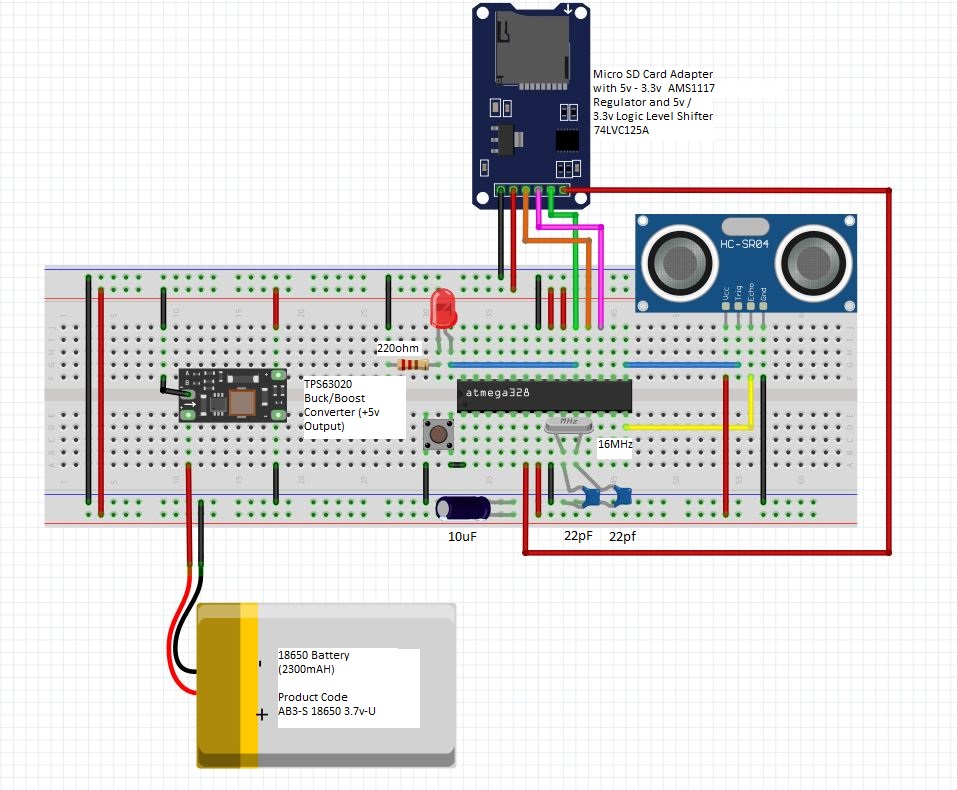
My issue has come about since I switched my power supply from the 5v/GND pins from the Uno board to being powered from a 18650 Lithium Battery boosted through a TPS63020 buck/boost converter board like this.

The SD card continues to log values absolutely fine however these values are all "0.00" rather that the readings that should be coming from the sensor hence I don't think the sensor is returning values correctly for some reason.

I initially thought it might be noise from the boost converter however I tried connecting a USB cable 5v and GND wires from my laptop to the input of the voltage converter and it worked fine. I then thought it might be that with the USB input the the voltage converter being the same as the output it may reduce the noise so I took another buck converter set to an output of ~3.3v and connected the USB power supply to the inputs of that and the outputs to the boost converter and it also worked fine. I have also tried other boost modules using different IC's and circuit architectures non of which have worked with the battery but all of which have worked with the USB power supply.

Notes:
Battery I am using is this AB3-S 18650 2300mAh battery with PCB protected (though I have tried a range of other batteries).

Battery voltage is currently around 4.09v and does not drop by more than 0.02v when load is applied.

I have tried adding a couple of 1000uF electrolytic capacitors as in the past when I have had issues where modules draw short bursts of higher current, this has resolved the issue.

Essentially I am at a loss as to what is the issue and would really appreciate some advice. I have included the circuit setup (with the battery) and the code I am using below. Hopefully it all makes sense but feel free to ask questions if not.

#include <LowPower.h>
#include <SD.h>

// HC-SR04 sensor pins
const int trigPin = 9;   // Trigger pin for HC-SR04
const int echoPin = 8;   // Echo pin for HC-SR04 (moved from pin 10)

// SD card module chip select pin
// Arduino connections for SD card module:
//   - VCC to 5V
//   - GND to GND
//   - MOSI to pin 11
//   - MISO to pin 12
//   - SCK to pin 13
//   - CS  to pin 4 (you can change this if needed)
const int chipSelect = 4;

void setup() {
  // Start serial communication for debugging/logging
  Serial.begin(9600);
  
  // Set sensor pins
  pinMode(trigPin, OUTPUT);
  pinMode(echoPin, INPUT);
  
  // Initialize the SD card
  if (!SD.begin(chipSelect)) {
    Serial.println("SD card initialization failed!");
    // If SD card fails, halt execution.
    while (1);
  }
  Serial.println("SD card initialized.");
 
}

void loop() {
  const int numReadings = 30;
  float distances[numReadings];

  // Collect 30 sensor readings
  for (int i = 0; i < numReadings; i++) {
    // Ensure the trigger pin is LOW
    digitalWrite(trigPin, LOW);
    delayMicroseconds(2);

    // Trigger the sensor with a 10µs HIGH pulse
    digitalWrite(trigPin, HIGH);
    delayMicroseconds(10);
    digitalWrite(trigPin, LOW);

    // Read the echo pulse (timeout set to 30000 microseconds)
    long duration = pulseIn(echoPin, HIGH, 30000);

    // Convert duration (microseconds) to distance (in millimeters).
    // Calculation: distance = duration * (0.343 mm/us / 2) = duration * 0.1715.
    float distance = duration * 0.1715;
    distances[i] = distance;
    
    delay(50);  // Short delay between readings
  }

  // Sort the array using bubble sort to compute the median.
  for (int i = 0; i < numReadings - 1; i++) {
    for (int j = 0; j < numReadings - i - 1; j++) {
      if (distances[j] > distances[j + 1]) {
        float temp = distances[j];
        distances[j] = distances[j + 1];
        distances[j + 1] = temp;
      }
    }
  }

  // Calculate the median.
  float median;
  if (numReadings % 2 == 0) {
    median = (distances[numReadings / 2 - 1] + distances[numReadings / 2]) / 2.0;
  } else {
    median = distances[numReadings / 2];
  }
  
  // Print the median distance to the Serial Monitor.
  Serial.print("Median Distance: ");
  Serial.print(median);
  Serial.println(" mm");
  
  // Log the median result to the SD card BEFORE the delay.
  logData(median);
  
  // Added delay so the serial monitor can finish printing before sleeping.
  delay(50);

  // Enter low power mode for approximately 30 seconds.
  // Three cycles of 8 seconds (24 sec) + one cycle of 4 seconds (4 sec) + one cycle of 2 seconds (2 sec) = 30 seconds.
  for (int i = 0; i < 1; i++) {
    LowPower.powerDown(SLEEP_8S, ADC_OFF, BOD_OFF);
  }
  LowPower.powerDown(SLEEP_4S, ADC_OFF, BOD_OFF);
  //LowPower.powerDown(SLEEP_2S, ADC_OFF, BOD_OFF);
}

void logData(float medianValue) {
  // Open the file in append mode. It will be created if it doesn't exist.
  File dataFile = SD.open("datalog.txt", FILE_WRITE);
  if (dataFile) {
    // Log the median distance to the file.
    dataFile.print("Median Distance: ");
    dataFile.print(medianValue);
    dataFile.println(" mm");
    dataFile.close();  // Ensure data is written by closing the file.
    Serial.println("Data logged to SD card.");
  } else {
    Serial.println("Error opening datalog.txt");
  }
}

Apologies. I had made a drawing error in drawing up the layout please see the actual connection for this wire (it is in fact connected to ground)

I cannot find any decoupling caps for the 328, but you have them in your real circuit?

A bit more than needed, but if it does the job, sure :upside_down_face:

Do you have a link to where you bought the TPS?

You probably have some high frequency noise and a large capacitor is like trying to catch a mosquito with a tennis net. A mosquito net works better, why it has small holes that will not allow the bug through. You need high frequency capacitors as well as some bulk. You are only adding bulk.

Hi The TPS is bought from AliExpress https://www.aliexpress.com/item/1005006167904909.html?spm=a2g0o.productlist.main.3.4aab8586LLFD6f&algo_pvid=24c8bcbd-5c6a-414c-bc50-6583f155922d&algo_exp_id=24c8bcbd-5c6a-414c-bc50-6583f155922d-2&pdp_ext_f={"order"%3A"163"%2C"eval"%3A"1"}&pdp_npi=4%40dis!GBP!1.75!1.75!!!2.19!2.19!%402103835e17414833081498673eaa0e!12000036084365766!sea!UK!4681648323!X&curPageLogUid=35th9FvVXXFe&utparam-url=scene%3Asearch|query_from%3A

I love the tennis racket fly swotter analogy that makes a lot of sense. Would something like a 22pF ceramic cap do the job do you think? I will give it a try.

Do you have any idea why the high frequency noise would cause issues when powered from a battery but not from a usb? I am assuming that something about the usb power supply damps the occilations?

Just to confirm I have added a 22pF ceramic capacitor between the 5v and GND rails on the breadboard close to where the HC-SR04 connects and there is no change in how it performs. It still works flawlessly when connected to any USB power supply but reads 0mm whenever any batteries are used to power the boost converter.

Not really sure what else to try. I read somewhere that the HC-SR04 with a 4MHz crystal sometimes doesn't work well when powered with anything more than 4.9V (not sure it this is true and if so why) but in both the battery and USB powered scenarios the voltage provided by the boost converter is the same (4.98V) and it works fine when it is powered from the USB.

Any other suggestions would be greatly appreciated. I am going to try and throw together a basic oscilloscope with my spare Uno (as I dont really want to shell out £100+ for a proper scope) and see what that can read on the trig and echo pins of the HC-SR04 (I am guessing the high frequency noise will be above the sample rate I can get with an uno)

Speaking of mosquitoes... :grin: 0.1 - 1 uF will work a lot better, if your problem is noise. But you can always add one, it's not gonna harm.

Can you put together a more detailed diagram, centered around the 328p? I'd like to see the bypass capacitors etc. Also, how do you connect a stand alone 328p to USB?

1 Like

Hi, Sorry I am not understanding. Where should the bypass capacitors your are referring to be?

Below is an updated schematic with the 22pF cap across the 5v/Rails adjacent to the HC-SR04 connection I will go hunt for a cap around 0.1uF - 1uF and see if that makes a difference. Should there be additional caps somewhere else? If so where and what values would be recommended?

In terms of when it is connected to a usb power supply. Essentially it is a USB cable with one end cut off it and the 5v and GND wires broken out and connected as shown below. I just plug this into my computer or a usb wall socket. Appreciate it is rather quick and dirty as a power supply but it has worked well for me in the past and seems to work fine for this as well.

I built a Arduino oscilloscope with my spare Uno based on this set up Arduino oscilloscope with 7 lines of code which did not give me all that much useful info other than verifying that the signals on the Echo and Trig pins of the HC-SR04 do the same thing in both the battery powered and usb powered configs. (I doubt it samples fast enough to pick up HF noise).

It did however turn up something very odd which was that when the GND from the uno was connected to the ground rail of the breadboard, it caused it to work properly (irrespective of whether A0 as the sample probe was connected to a testing point). This made no sense to me but I did wonder if there is something going on in the battery powered config that means it is not pulling the GND rail fully to GND (but I dont know what this could be) and I dont know how I would go about testing it.

Ok further weirdness (i.e. I dont understand why). I noticed that while holding with bare hands, the bare end of a wire connected to the ground rail on the breadboard the circuit also worked perfectly. Is this by any chance because I am acting as a capacitor in some way.

I believe you confuse the 22pF that is common to use with a crystal, with the decoupling capacitor(s) that are used to filter out the noise digital IC's usually produce, as well as act as a tiny energy reserve.

This is the decoupling caps, for both Vcc and AVcc

How you build a xtal (external clock) circuit I leave out, you're already on track with that one.

1 Like

Sure, that's how you can get good signal in your radio also. But it's not supposed to be that way :smiley:

If you wanna do more electronics, I encourage your to buy a bunch of MLCC 0.1 and 1 uF capacitors. Those values and type are very common. But get them from reputable source. Sources like where you got the TPS from can be questionable. Which leads me to:

Have you figured out the problem yet? Circuit works fine with USB power, and not with the TPS. There's already a bunch of caps on that regulator, so you'd think they had that under control, and not that you have to add filter capacitors. I prefer Mouser, but DigiKey, Farnell and RS components also have a solid reputation. Neither of those are cheap, but on the other hand you always know that you get quality.

Anything with a clock can cause the problem such as the Buck Converter, processor etc.

1 Like

Ah ok, thankyou! That makes much more sense. I will order some 0.1uF and 1uF caps and give that a try. I assume they should be as close as possible to the AVCC and VCC pins as possible?

I'm still a bit confused as to whether you think it is the converter or the processor or the HC-SR04 that is creating the noise that is causing the issue.

In terms of the TPS and the other boost converter I have tried which is a MT3608 (See link at bottom), the circuit works fine when USB 5v and GND is fed into the VIN and GND respectively (not strictly needed as I understand it as the USB is already 5v) but I dont understand why that would not also produce problematic HF noise if the converters were creating that when the converter was connected to a battery?

I really appreciate your efforts to help. :slight_smile:

1 Like

Correct.

Different voltages, it shifts certain parameters, like frequency, PWM.

Edit: One more possibility is that the TPS chip can be counterfate or another chip, rebadged. You never know with those Chinese products.

Check this video it explains how they work and you will see where the switching is. https://www.youtube.com/watch?v=W6NOV6b8kxs

Also consider a SEPIC converter (Single-Ended Primary Inductor Converter) , that will give you a lot more room on the battery. Your layout on proto board gives you lots of antennas, it is possible the noise is coming from somewhere else.

1 Like

Cheers for the suggestion regarding the external RF noise and the video link. Really interesting to see how the switching converters work. I have tried moving it away from any obvious significant nearby sources of RF noise (My laptop, laptop charger, screens, phone chargers etc but no change - obviously it could be RF noise from other sources etc). I will have a look at the SEPIC.

I have also ordered a bunch of MLCC's of a range of values including 0.1uf and 1uf so I will provide an update when these get here fingers crossed it solves it. Am I correct in saying it would also be worth putting a couple of 0.1uf caps from VCC to GND on the HC-SR04 and SD card module connection pins and also close to the output of the converter to reduce noise associated with and affecting these?

You will get it! The shorter the wires the less they will pick up. Also if that proto board is used you may have some loose connections causing problems as well. My proto boards power rails are open in the middle and I need to add jumpers. Approximately where your button is, the top and bottom two.

Through all your testing I think you have isolated the problem to the battery.
Have you tried a different battery?