Hi, Sorry I am not understanding. Where should the bypass capacitors your are referring to be?
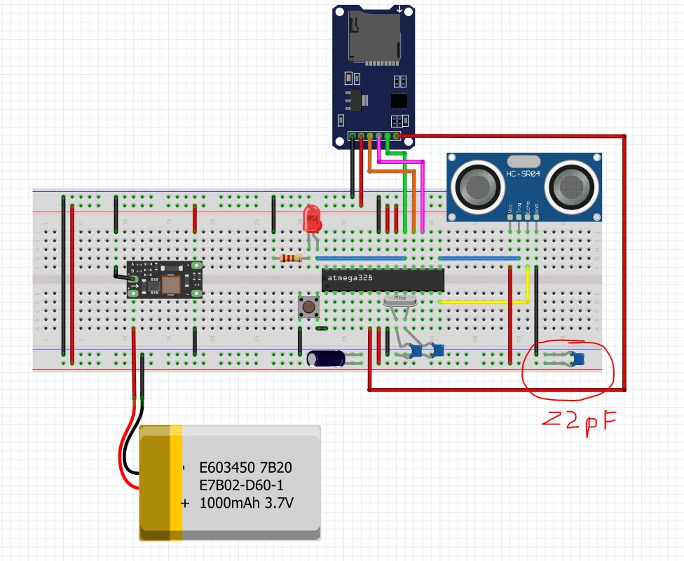
Below is an updated schematic with the 22pF cap across the 5v/Rails adjacent to the HC-SR04 connection I will go hunt for a cap around 0.1uF - 1uF and see if that makes a difference. Should there be additional caps somewhere else? If so where and what values would be recommended?
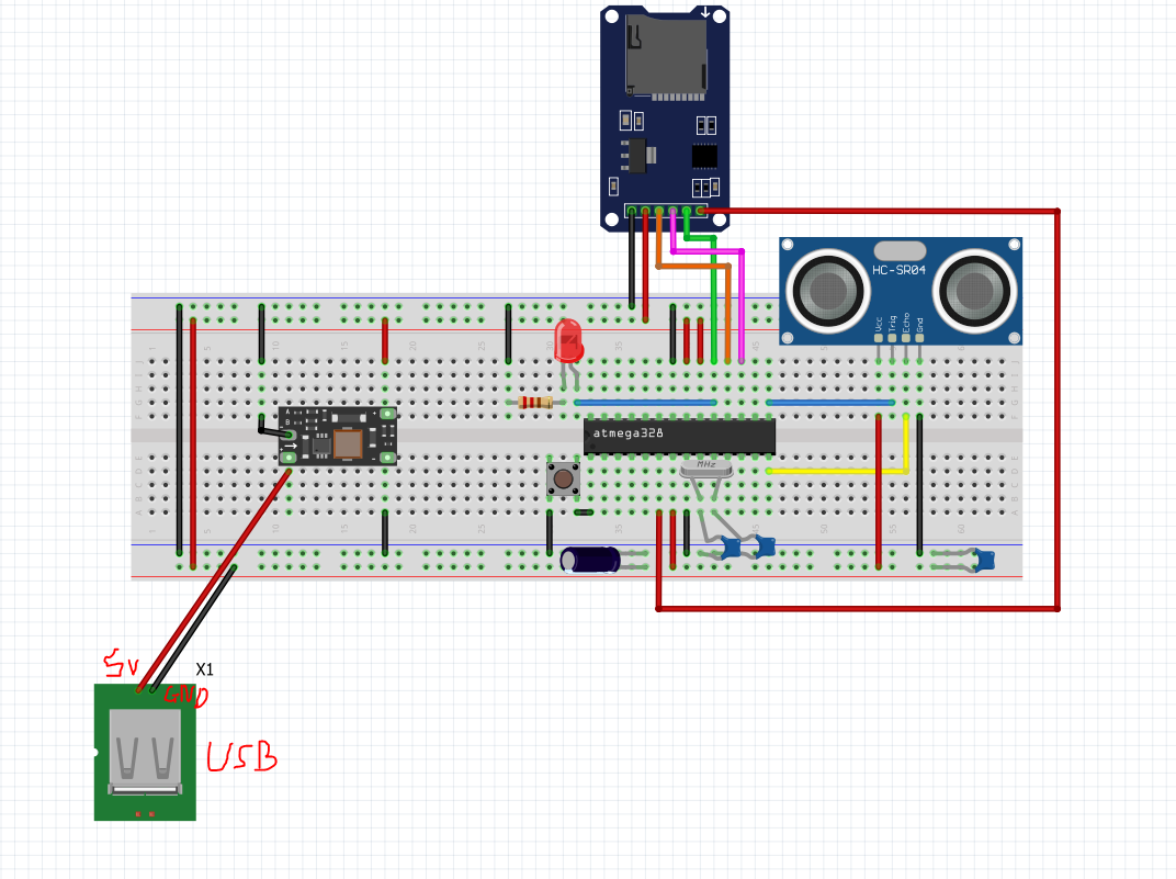
In terms of when it is connected to a usb power supply. Essentially it is a USB cable with one end cut off it and the 5v and GND wires broken out and connected as shown below. I just plug this into my computer or a usb wall socket. Appreciate it is rather quick and dirty as a power supply but it has worked well for me in the past and seems to work fine for this as well.
I built a Arduino oscilloscope with my spare Uno based on this set up Arduino oscilloscope with 7 lines of code which did not give me all that much useful info other than verifying that the signals on the Echo and Trig pins of the HC-SR04 do the same thing in both the battery powered and usb powered configs. (I doubt it samples fast enough to pick up HF noise).
It did however turn up something very odd which was that when the GND from the uno was connected to the ground rail of the breadboard, it caused it to work properly (irrespective of whether A0 as the sample probe was connected to a testing point). This made no sense to me but I did wonder if there is something going on in the battery powered config that means it is not pulling the GND rail fully to GND (but I dont know what this could be) and I dont know how I would go about testing it.