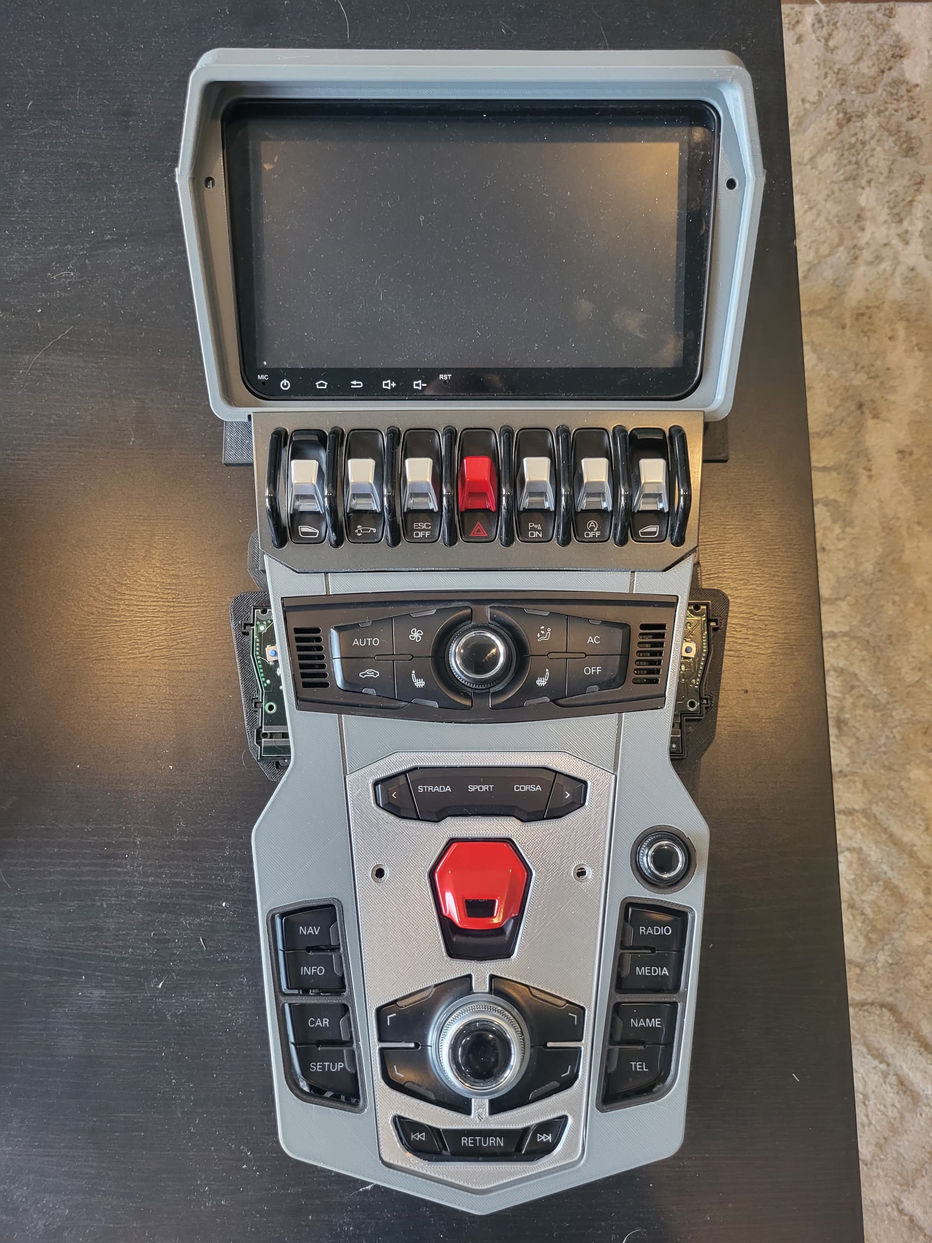
Quick background... I'm building a replica Lamborghini Aventador and need to hack an Audi component. Specifically, I'm planning on using the buttons from an Audi infotainment system to control a generic Android radio/nav system. (My prototype center console looks quite similar to the Aventador center console, but uses a mix of Audi and Lamborghini components, combined with various 3d printed parts). Ultimately, when a button (or control) is touched, the button module will send an rs232 serial code sequence that is picked up by an Arduino Mega. The Mega would then simulate a steering wheel button being pressed, which could be mapped to the Android controls.
In order to achieve this, I need to see what codes the button module produces when buttons are pushed and what responses are sent from the Audi control head. As such, I tapped into the two rs232 data lines between the button module and the control head, connecting them to two Mega serial connections through max232 modules. I then display this with a serial connection to the pc. With everything turned on, the button unit operates correctly. Leds indicate which button has been pushed. I get a good data stream from the control head every time a button is pushed, which gives me the codes required to turn the button leds on and off.
However (finally getting to my issue), I don't get any data from the button module!?! I should receive 7 bytes of data indicating which button (or dial) has been touched. But I get nothing. I know it's sending data since the control head is responding...I'm just not reading anything.
If I swap the two data lines between the two max232 modules, I get the exact same results (just with serial1 and serial2 reversed). At this point, I thought that it was a bad wire from the button module Tx line... however, one occurrence indicates that is not the case. If the units are left long enough they drop into a low power mode. The control head then sends a shut down sequence. At this point, if I push a button, I do get the codes from the button module telling me which button has been pressed. The control head then sends a start sequence of codes that initialize the button module. Then I'm right back to being able to read the data stream from the control head, but nothing else from the button module.
This appears to be a hardware "issue". Are there any electronics guys who can explain it? What is the solution so that I can read both data streams?
Yes. The devices are communicating using rs232, running at 9600 baud.
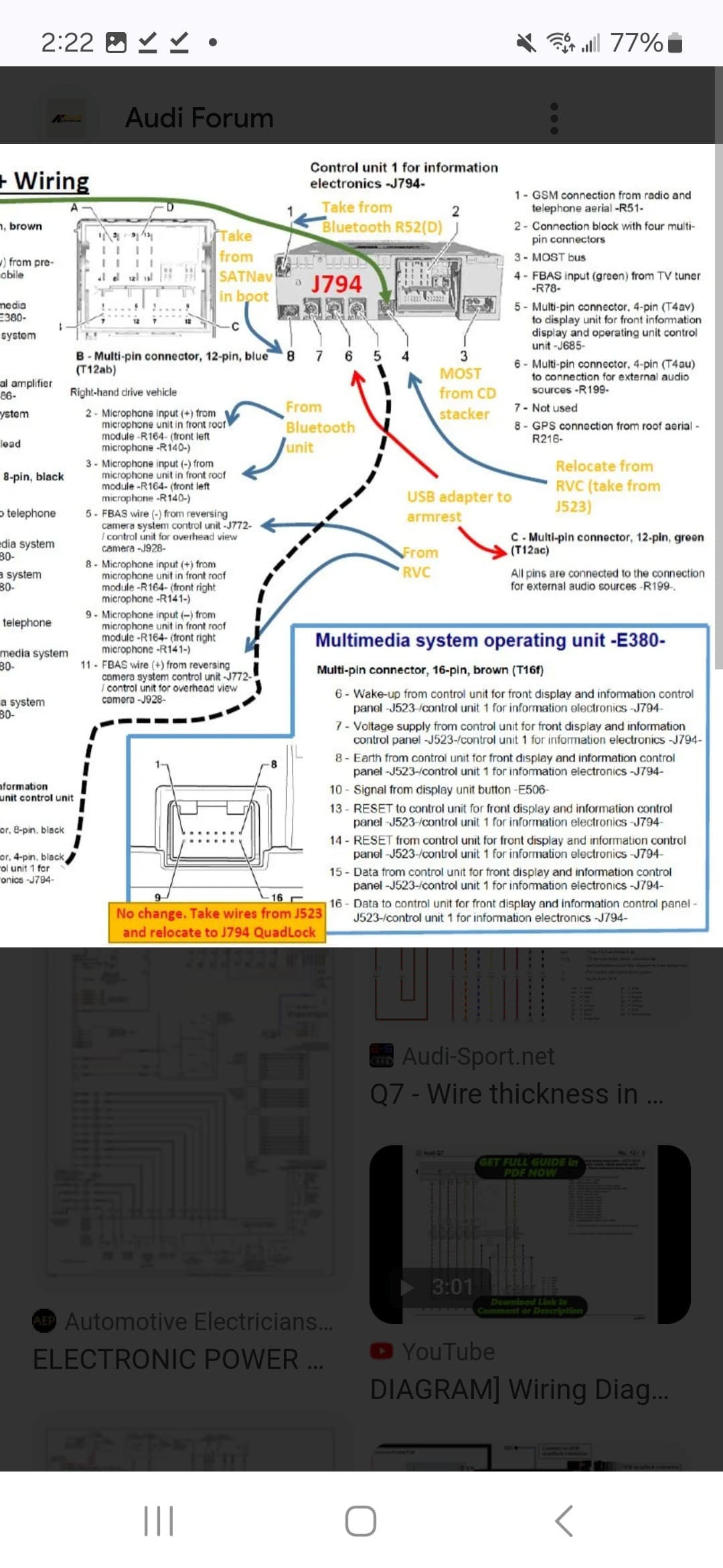
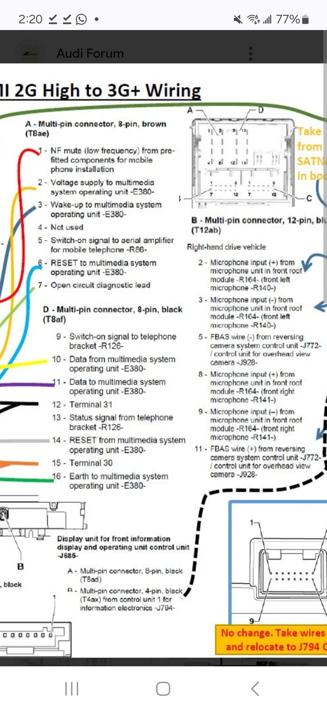
The two modules are the Audi E380 (buttons/ volumn/ joystick) and the Audi J794 (MMI control head). The J794 connects to the rest of the car (which I don't have, incidentally) using CanBus, and the rest of the audio equipment through a MOST fiberoptic loop. The E380 and J794 are connected by 7 wires. Power, ground, wakeup, E380 reset, J794 reset and the two rs232 data lines (Rx and Tx).
As mentioned, I do read the E380 data while the J794 is shut down. I just can't read the data from the E380 when the J794 is awake.
(Note: I'm currently away from my house for the next 5 days, so I can't take any pictures of the setup)
There isn't much useful documentation out there, unfortunately. Though I did find a screen shot of some E380 data, which matches the data format that I've read myself. The checksums also add up correctly.
There is no question about the communication type and baud rate.
Yes. This is the simple plan.... but for some reason the E380 Tx doesn't want to be read, even though I know it's got to have data there because the J794 is responding to it.
The only thing I didn't try was scoping this line while I can't read it. When I get home I will certainly do that... not sure what that's going to get me other than to prove the data is there.
Hmmmm.... accidentally deleted my last post. That wasn't my intention... I'll just rewrite it.
I spent some time with the oscilloscope and discovered some things. Firstly, despite all documentation and a number of Audi "experts" stating that the communication between the E380 and J794 is rs232.... it's not. Admittedly, I took all the available info to be correct without actually checking it myself. As a mechanical engineer, I clearly didn't understand rs232 requirements. For those that asked if it actually was rs232, you were definitely on the right track. The fact that the Max232 interface was reading almost everything, just further confirmed it as being rs232 when it wasn't.
Of course, now I'm stuck. The J794 data stream is running from 0v to 5v. The E380, however, is running from about 2.8v to 4.8v. I don't know of any protocol that uses that range.
Both are just straight digital data streams. You will need your logic analyzer to determine the structure. The 0 to 5 volts is TTL, standard for generations. The other could be modified to also be TTL. But the bit structure and timing are unknown.
The timing and bit structure don't seem to be a problem. It's definitely running at 9600 baud and there were times that I could read the data using the max232. Before I bought the J794, I was able to read the E380 using the max232. Unfortunately, I could only read the two dials and the joystick. The buttons didn't seem to do anything. The data structure also matched something that someone had posted about 7 years ago on an Audi site. Checksums calculate correctly. So really my only issue seems (to me.... though I've already proven I clearly don't know what I'm talking about) to be the voltage issue. Can the voltages be adjusted without affecting the timing?
Unfortunately, I have different models for the J794 and E380 than what is shown in that document. I wish they hadn't used the same name for the parts. My pins are quite different. I've gone through dozens of tech documents and they all show the pins as "data to" and "data from" with respect to the connection between these particular models. The CanBus lines don't go to the E380. I've worked with CanBus and it is a differential signal. When I scope these two lines (and there aren't any extra pins that I haven't accounted for) they are clearly two separate serial lines. When a button is pushed, I get a serial data signal from the E380 on one line and then I get a response from the J794 on the other line. If it were a CanBus signal I would see a differential signal on both lines as each unit talks. I'm not sure how to post pictures, otherwise I could show pics of everything. The E380 has 7 pins. 12v, gnd, wakeup, reset to J794, reset to E380, data to and data from.
Now, having said all that.... the data signal from the E380 does look like half a CanBus (differential) signal... but definitely not CanBus protocol.
I opened the E380. It uses a Motorola MC68HC08AZ60A. I went through the documentation, but I couldn't pull out anything overly useful. It does have a CanRx pin and a CanTx pin, as well as a Tx pin and a Rx pin. The CanTx pin is not connected to anything (external to the chip). The Tx, Rx and CanRx pins are connected to the two data lines. Engineers don't make anything simple (I know... I'm an Engineer ). Of course, there could be CanBus controller external to the chip using the Tx line, but this doesn't seem likely... of course, I'm not exactly batting 1000 with my declarations up to now.
Just wanted to give a quick update. I set up a small comparator circuit using an LM393. I set the reference voltage to 3.8v (mid-point between the 2.8v low and 4.8v high). Used a pull up resistor to set the high output at 5v. This essentially converted the serial data to a TTL signal which the Mega had no problem reading.
Just discovered that there is something called SWCAN, single- wire CanBus. Sometimes used on automotive applications. It works at a slower speed than regular CanBus, and is the fallback for two wire CanBus systems if one of the two wires gets broken.
I'm happy with my comparator approach, so I won't bother building any thing else.