Issue with ADC for electret microphone (without amplification)

Hello! Before I start I would just like to apologize in advance if I poorly understand how some of these components or circuits are supposed to function. Being relatively new to this wonderful field of electronics, it's suffice to say that this is inevitable. Please feel free to correct me on anything incorrectly stated!

So... my ultimate project is to create my own "clapper" that you can plug any appliance into and simply turn on by clapping twice. My first plan of attack was handling the capture of the sound, using a microphone and an Arduino UNO (which would consequently trigger a relay once the appropiate analog response from the mic was reached).

I like using some components from older appliances that are collecting dust in my house, so I took apart an old at&t answering system (model 1739) and pulled out this microphone (couldn't find any datasheet for the circuit board, so no idea the exact characteristics of the mic):


Not knowing too much (i.e. anything) about mics, I did research... and came to the conclusion that this must be an electret microphone. Now I am not 100% sure, but given the overall look and widespread use of these I feel confident about it (hopefully this is not the part that I am wrong in... :o :o ) Also I see a little bit of what I believe to be a green PCB layout on the back, which is where I assume the FET impedance converter would be located if it was electret.

So here is my simple circuit drawn out (as well as breadboard connections) without any gain amplification that I connected to the A0 analog pin of the arduino UNO.

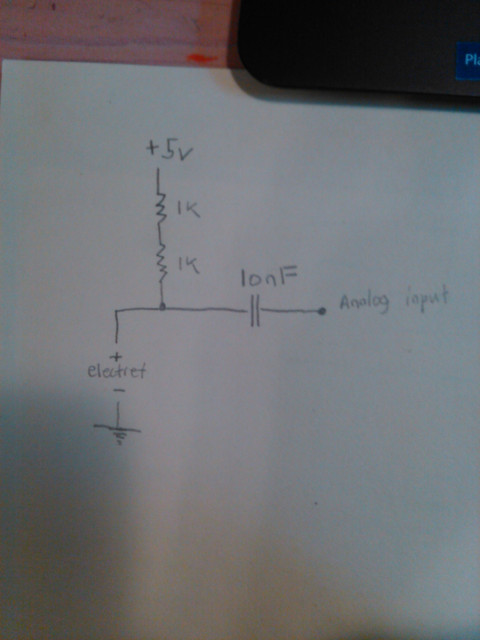
I used 2k resistance as this seems to be roughly the value used for biasiing the electret's JFET. As the way I understand it, the capacitor allows the AC voltage from the electret microphone to pass (within mVs range) while blocking the DC current to the analog input.

Powering this from a a 5V wall adapter, the circuit seems to work. On my oscilloscope, I see low voltage waveforms from clapping, speaking, music etc.

However, the issue comes from inputting these signals into the ADC of the ATMega328
(datasheet)

Here is my simple code for checking the analog voltage:

void setup() {
Serial.begin(9600);
}

void loop() {
int reading = analogRead(A0);
Serial.println(reading);
}

What I get on the serial monitor are much higher voltages that slowly decline over time. Removing the A0 input and grounding the capacitor and plugging back the A0 connection brings the reading to roughly ~30, which then increases with time (video link: VID 20190805 170618 342 - YouTube)

Suffice to say... I am a bit perplexed.

I know that the ADC datasheet recommends a low impedance source with a slowly varying signal, but I figured the impedance conversion circuit already included in the electet capsule provides this, and as for slowly varying signal... I tried an RC low pass filter and the same effects occur. I feel like I am missing something obvious here... I even tried an OP amp buffer to have an even smaller source impedance but it didn't have an effect.

I don't get why the S/H capacitor would charge up to almost 4.5V...and then very slowly trickle down. It should only see mV's from the mic. Perhaps it's because I'm powering the mic with +5V from the arduino? Still, by looking at the analog input circuitry I still don't quite understand why that would matter...

Would anyone like to shed light on this mystery? I'd really like to understand the circuitry behind why this is happening. Or just a nudge in the right direction so I can search more on my own. I feel like what I'm looking up isn't very useful. If it's just a simple overlook sorry!!

Thank you!
-Justin

image uploader

The capacitor is connected to a very high impedance point - the analog input. You need a pull down on the analog input .
Also the signal into the A/D is an AC waveform - that is unsuitable and may damage the Arduino.
I suspect the internal protection diodes and clamping the waveform in one direction resulting in the capacitor charging. There will also be a switch on spike , which will only discharge slowly.

The capacitor is connected to a very high impedance point - the analog input. You need a pull down on the analog input

Do you mean something like this? Is the point of the resistor (just assuming a 1k would be fine) to discharge the S/H capacitor after switching back to the input signal?

Also the signal into the A/D is an AC waveform - that is unsuitable and may damage the Arduino.
I suspect the internal protection diodes and clamping the waveform in one direction resulting in the capacitor charging.

I read a little bit about op amp biasing to push an input signal above ground by a fixed amount. This would be the fix for the AC coming from the electret wouldn't it?

There will also be a switch on spike , which will only discharge slowly.

With the pulldown resistor added I am thinking this would take care of this?

Thanks for the help!

The pull down resistor will help.

I would go for amplifying and rectifying the signal. If you google “ op amp precision rectifier “ you’ll get some circuits.

There are lots of problems with your approach.

  1. The resolution of the ADC, using a 5V reference, is about 5 mV. The microphone output may not vary by much more than that, so you need an amplifier, or use the 1.1V reference to get about 1 mV resolution.

  2. Use a larger load resistor on the microphone, to get more output variation. 10K is common.

  3. In your test program, the sampling rate is determined by the serial Baud rate, which (at 9600) is very low. You are sampling the microphone output only about 200 times per second, so it is unlikely that you will detect an impulsive sound like a clap.

  4. You don't need a capacitor, pulldown or bias resistor if the microphone power supply voltage is less than or equal to the analog voltage reference.

I recommend to get an amplified microphone module like this one: SparkFun Electret Microphone Breakout - BOB-12758 - SparkFun Electronics.

hammy:
The pull down resistor will help.

I would go for amplifying and rectifying the signal. If you google “ op amp precision rectifier “ you’ll get some circuits.

ahh yes this is definitely a more efficient design. But for my purposes and after running some tests the DC offset added to the AC signal works well enough for me. perhaps version 2.0 I will go this route :slight_smile:

jremington:

  1. The resolution of the ADC, using a 5V reference, is about 5 mV. The microphone output may not vary by much more than that, so you need an amplifier, or use the 1.1V reference to get about 1 mV resolution.

So this is what I came up with including the relay circuit:

It works fairly well to just detect a clap! (I followed this pre-amp design, substituting in slightly different values for the capacitors/resistors with what I had on hand. I also added a low pass filter to hopefully cut the ADC some slack and avoid high frequency signals.

Here's a youtube video of it in action with smacking the table instead of clapping (which also works)

jremington:
3. In your test program, the sampling rate is determined by the serial Baud rate, which (at 9600) is very low. You are sampling the microphone output only about 200 times per second, so it is unlikely that you will detect an impulsive sound like a clap.

Thanks for this!! That definitely improved detection.

jremington:
4. You don't need a capacitor, pulldown or bias resistor if the microphone power supply voltage is less than or equal to the analog voltage reference.

It seems to me that popping in that extra 100k resistor actually got rid of the slowly rising analog values seen on the serial plotter. Even after the amplification stage and getting rid of below 0 ground signals they still seemed to slowly rise until I put this resistor in parallel.

jremington:
I recommend to get an amplified microphone module like this one: SparkFun Electret Microphone Breakout - BOB-12758 - SparkFun Electronics.

awwwww that's no fun! ;D but honestly I prefer making my own setup from discrete components for whatever project i'm working on (with some exceptions of course). I feel like I learn a lot more, and even though it's generally shit compared to the commercially sold package, I'm more proud... (and I don't have to spend any money!)

Here is the detection clap code for anyone interested. It's not great but it works. I was just trying to find a balance between having high sensitivity to hear a clap, but also avoiding detection for any ambient sounds (talking, music, etc.). If anyone has any suggestions feel free to let me know. My approach to coding is very haphazard haha so I'm sure that there are glaring flaws in the structure.

int reading;
bool clap1=false;
bool clap2=false;
unsigned long checkClap;
unsigned long currentTimer;
int clapShortInterval=500;
int clapLongInterval=2000;
int silenceShortInterval=200;
int silenceLongInterval=1000;
int lowerLimit = 330;
int higherLimit = 540;

void setup() {
  
Serial.begin(115200);

pinMode(2,OUTPUT);
digitalWrite(2,LOW);

pinMode(LED_BUILTIN,OUTPUT);
digitalWrite(LED_BUILTIN,LOW);

}

void loop() {  

checkReading();
triggerRelay();

}


void switchRelay(){
 if (digitalRead(LED_BUILTIN)==HIGH){
  digitalWrite(LED_BUILTIN,LOW);
  digitalWrite(2,LOW);
}
else{
  digitalWrite(LED_BUILTIN,HIGH); 
  digitalWrite(2,HIGH);
}
}

void checkReading(){
reading = analogRead(A3);
Serial.println(reading);
}


void triggerRelay(){
  
if ((reading > higherLimit || reading < lowerLimit) && clap1==false && clap2==false){
  clap1=true;
  checkClap=millis();
}

while(clap1==true){
  currentTimer=millis();
  if (currentTimer-checkClap>=clapShortInterval && currentTimer-checkClap<= clapLongInterval){
    checkReading();
    if ((reading > higherLimit || reading < lowerLimit)&& clap2==false){
      clap2=true;
      clap1=false;
      checkClap=millis();
    }
  }
  else if (currentTimer-checkClap>clapLongInterval){
    clap1=false;
  }
}


while(clap2==true){
  currentTimer=millis();
  if (currentTimer-checkClap>=silenceShortInterval){
    checkReading();
    if (currentTimer-checkClap>=silenceLongInterval){
        switchRelay();
        clap2=false;
    }
      else if(reading > higherLimit || reading < lowerLimit && currentTimer-checkClap<silenceLongInterval ){
        clap2=false;
      }
    }
  }
}

Anyway thanks for your help guys!

Relay circuit is wrong. Now the relay is getting about 3.5volt, and might not work reliably.

Relay coil must be connected between 5volt and collector, with emitter of the transistor to ground.
Must use a kickback diode (1N4148, 1N4004) across the relay coil to protect the transistor, cathode/ring too 5volt.
The indicator LED (without resistor) could go in the base line.
The 500ohm base resistor then has the double function of limiting base current as well as LED current.
Leo..