Update: -
We have done some other testings.
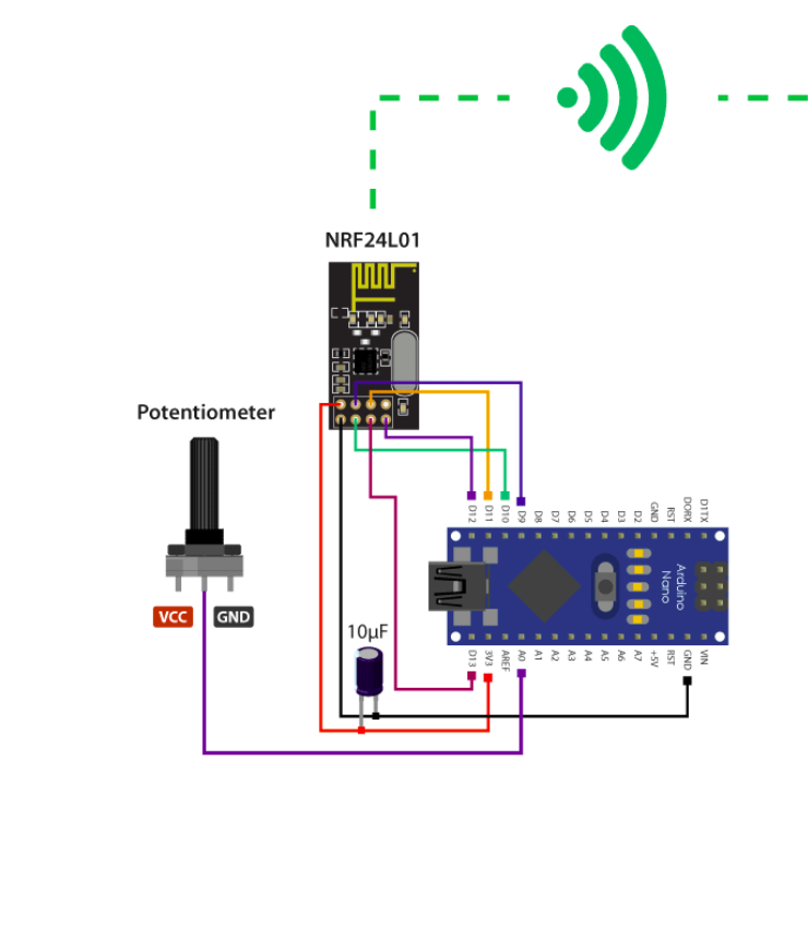
This is a circuit of transmitter to check servo motor operation. (Image 1)
However, we have made some necessary changes in this circuit. In our test, we didn't use MPU6050 in transmitter circuit. So our circuit looks like this (Image 2).
We have not made any changes in the code and used it as provided by the image 1 circuit developer.
Code of Transmitter :-
/*
        DIY Arduino based RC Transmitter
  by Dejan Nedelkovski, www.HowToMechatronics.com
  Library: TMRh20/RF24, https://github.com/tmrh20/RF24/
*/

#include <SPI.h>
#include <nRF24L01.h>
#include <RF24.h>
#include <Wire.h>


// Define the digital inputs
#define jB1 1  // Joystick button 1
#define jB2 0  // Joystick button 2
#define t1 7   // Toggle switch 1
#define t2 4   // Toggle switch 1
#define b1 8   // Button 1
#define b2 9   // Button 2
#define b3 2   // Button 3
#define b4 3   // Button 4

const int MPU = 0x68; // MPU6050 I2C address
float AccX, AccY, AccZ;
float GyroX, GyroY, GyroZ;
float accAngleX, accAngleY, gyroAngleX, gyroAngleY;
float angleX, angleY;
float AccErrorX, AccErrorY, GyroErrorX, GyroErrorY;
float elapsedTime, currentTime, previousTime;
int c = 0;


RF24 radio(5, 6);   // nRF24L01 (CE, CSN)
const byte address[6] = "00001"; // Address

// Max size of this struct is 32 bytes - NRF24L01 buffer limit
struct Data_Package {
  byte j1PotX;
  byte j1PotY;
  byte j1Button;
  byte j2PotX;
  byte j2PotY;
  byte j2Button;
  byte pot1;
  byte pot2;
  byte tSwitch1;
  byte tSwitch2;
  byte button1;
  byte button2;
  byte button3;
  byte button4;
};

Data_Package data; //Create a variable with the above structure

void setup() {
  Serial.begin(9600);

  // Initialize interface to the MPU6050
  initialize_MPU6050();

  // Call this function if you need to get the IMU error values for your module
  //calculate_IMU_error();

  // Define the radio communication
  radio.begin();
  radio.openWritingPipe(address);
  radio.setAutoAck(false);
  radio.setDataRate(RF24_250KBPS);
  radio.setPALevel(RF24_PA_LOW);

  // Activate the Arduino internal pull-up resistors
  pinMode(jB1, INPUT_PULLUP);
  pinMode(jB2, INPUT_PULLUP);
  pinMode(t1, INPUT_PULLUP);
  pinMode(t2, INPUT_PULLUP);
  pinMode(b1, INPUT_PULLUP);
  pinMode(b2, INPUT_PULLUP);
  pinMode(b3, INPUT_PULLUP);
  pinMode(b4, INPUT_PULLUP);

  // Set initial default values
  data.j1PotX = 127; // Values from 0 to 255. When Joystick is in resting position, the value is in the middle, or 127. We actually map the pot value from 0 to 1023 to 0 to 255 because that's one BYTE value
  data.j1PotY = 127;
  data.j2PotX = 127;
  data.j2PotY = 127;
  data.j1Button = 1;
  data.j2Button = 1;
  data.pot1 = 1;
  data.pot2 = 1;
  data.tSwitch1 = 1;
  data.tSwitch2 = 1;
  data.button1 = 1;
  data.button2 = 1;
  data.button3 = 1;
  data.button4 = 1;
}
void loop() {
  // Read all analog inputs and map them to one Byte value
  data.j1PotX = map(analogRead(A1), 0, 1023, 0, 255); // Convert the analog read value from 0 to 1023 into a BYTE value from 0 to 255
  data.j1PotY = map(analogRead(A0), 0, 1023, 0, 255);
  data.j2PotX = map(analogRead(A2), 0, 1023, 0, 255);
  data.j2PotY = map(analogRead(A3), 0, 1023, 0, 255);
  data.pot1 = map(analogRead(A7), 0, 1023, 0, 255);
  data.pot2 = map(analogRead(A6), 0, 1023, 0, 255);
  // Read all digital inputs
  data.j1Button = digitalRead(jB1);
  data.j2Button = digitalRead(jB2);
  data.tSwitch2 = digitalRead(t2);
  data.button1 = digitalRead(b1);
  data.button2 = digitalRead(b2);
  data.button3 = digitalRead(b3);
  data.button4 = digitalRead(b4);
  // If toggle switch 1 is switched on
  if (digitalRead(t1) == 0) {
    read_IMU();    // Use MPU6050 instead of Joystick 1 for controling left, right, forward and backward movements
  }
  // Send the whole data from the structure to the receiver
  radio.write(&data, sizeof(Data_Package));
}

void initialize_MPU6050() {
  Wire.begin();                      // Initialize comunication
  Wire.beginTransmission(MPU);       // Start communication with MPU6050 // MPU=0x68
  Wire.write(0x6B);                  // Talk to the register 6B
  Wire.write(0x00);                  // Make reset - place a 0 into the 6B register
  Wire.endTransmission(true);        //end the transmission
  // Configure Accelerometer
  Wire.beginTransmission(MPU);
  Wire.write(0x1C);                  //Talk to the ACCEL_CONFIG register
  Wire.write(0x10);                  //Set the register bits as 00010000 (+/- 8g full scale range)
  Wire.endTransmission(true);
  // Configure Gyro
  Wire.beginTransmission(MPU);
  Wire.write(0x1B);                   // Talk to the GYRO_CONFIG register (1B hex)
  Wire.write(0x10);                   // Set the register bits as 00010000 (1000dps full scale)
  Wire.endTransmission(true);
}

void calculate_IMU_error() {
  // We can call this funtion in the setup section to calculate the accelerometer and gury data error. From here we will get the error values used in the above equations printed on the Serial Monitor.
  // Note that we should place the IMU flat in order to get the proper values, so that we then can the correct values
  // Read accelerometer values 200 times
  while (c < 200) {
    Wire.beginTransmission(MPU);
    Wire.write(0x3B);
    Wire.endTransmission(false);
    Wire.requestFrom(MPU, 6, true);
    AccX = (Wire.read() << 8 | Wire.read()) / 4096.0 ;
    AccY = (Wire.read() << 8 | Wire.read()) / 4096.0 ;
    AccZ = (Wire.read() << 8 | Wire.read()) / 4096.0 ;
    // Sum all readings
    AccErrorX = AccErrorX + ((atan((AccY) / sqrt(pow((AccX), 2) + pow((AccZ), 2))) * 180 / PI));
    AccErrorY = AccErrorY + ((atan(-1 * (AccX) / sqrt(pow((AccY), 2) + pow((AccZ), 2))) * 180 / PI));
    c++;
  }
  //Divide the sum by 200 to get the error value
  AccErrorX = AccErrorX / 200;
  AccErrorY = AccErrorY / 200;
  c = 0;
  // Read gyro values 200 times
  while (c < 200) {
    Wire.beginTransmission(MPU);
    Wire.write(0x43);
    Wire.endTransmission(false);
    Wire.requestFrom(MPU, 4, true);
    GyroX = Wire.read() << 8 | Wire.read();
    GyroY = Wire.read() << 8 | Wire.read();
    // Sum all readings
    GyroErrorX = GyroErrorX + (GyroX / 32.8);
    GyroErrorY = GyroErrorY + (GyroY / 32.8);
    c++;
  }
  //Divide the sum by 200 to get the error value
  GyroErrorX = GyroErrorX / 200;
  GyroErrorY = GyroErrorY / 200;
  // Print the error values on the Serial Monitor
  Serial.print("AccErrorX: ");
  Serial.println(AccErrorX);
  Serial.print("AccErrorY: ");
  Serial.println(AccErrorY);
  Serial.print("GyroErrorX: ");
  Serial.println(GyroErrorX);
  Serial.print("GyroErrorY: ");
  Serial.println(GyroErrorY);
}

void read_IMU() {
  // === Read acceleromter data === //
  Wire.beginTransmission(MPU);
  Wire.write(0x3B); // Start with register 0x3B (ACCEL_XOUT_H)
  Wire.endTransmission(false);
  Wire.requestFrom(MPU, 6, true); // Read 6 registers total, each axis value is stored in 2 registers
  //For a range of +-8g, we need to divide the raw values by 4096, according to the datasheet
  AccX = (Wire.read() << 8 | Wire.read()) / 4096.0; // X-axis value
  AccY = (Wire.read() << 8 | Wire.read()) / 4096.0; // Y-axis value
  AccZ = (Wire.read() << 8 | Wire.read()) / 4096.0; // Z-axis value

  // Calculating angle values using
  accAngleX = (atan(AccY / sqrt(pow(AccX, 2) + pow(AccZ, 2))) * 180 / PI) + 1.15; // AccErrorX ~(-1.15) See the calculate_IMU_error()custom function for more details
  accAngleY = (atan(-1 * AccX / sqrt(pow(AccY, 2) + pow(AccZ, 2))) * 180 / PI) - 0.52; // AccErrorX ~(0.5)

  // === Read gyro data === //
  previousTime = currentTime;        // Previous time is stored before the actual time read
  currentTime = millis();            // Current time actual time read
  elapsedTime = (currentTime - previousTime) / 1000;   // Divide by 1000 to get seconds
  Wire.beginTransmission(MPU);
  Wire.write(0x43); // Gyro data first register address 0x43
  Wire.endTransmission(false);
  Wire.requestFrom(MPU, 4, true); // Read 4 registers total, each axis value is stored in 2 registers
  GyroX = (Wire.read() << 8 | Wire.read()) / 32.8; // For a 1000dps range we have to divide first the raw value by 32.8, according to the datasheet
  GyroY = (Wire.read() << 8 | Wire.read()) / 32.8;
  GyroX = GyroX + 1.85; //// GyroErrorX ~(-1.85)
  GyroY = GyroY - 0.15; // GyroErrorY ~(0.15)
  // Currently the raw values are in degrees per seconds, deg/s, so we need to multiply by sendonds (s) to get the angle in degrees
  gyroAngleX = GyroX * elapsedTime;
  gyroAngleY = GyroY * elapsedTime;

  // Complementary filter - combine acceleromter and gyro angle values
  angleX = 0.98 * (angleX + gyroAngleX) + 0.02 * accAngleX;
  angleY = 0.98 * (angleY + gyroAngleY) + 0.02 * accAngleY;
  // Map the angle values from -90deg to +90 deg into values from 0 to 255, like the values we are getting from the Joystick
  data.j1PotX = map(angleX, -90, +90, 255, 0);
  data.j1PotY = map(angleY, -90, +90, 0, 255);
}
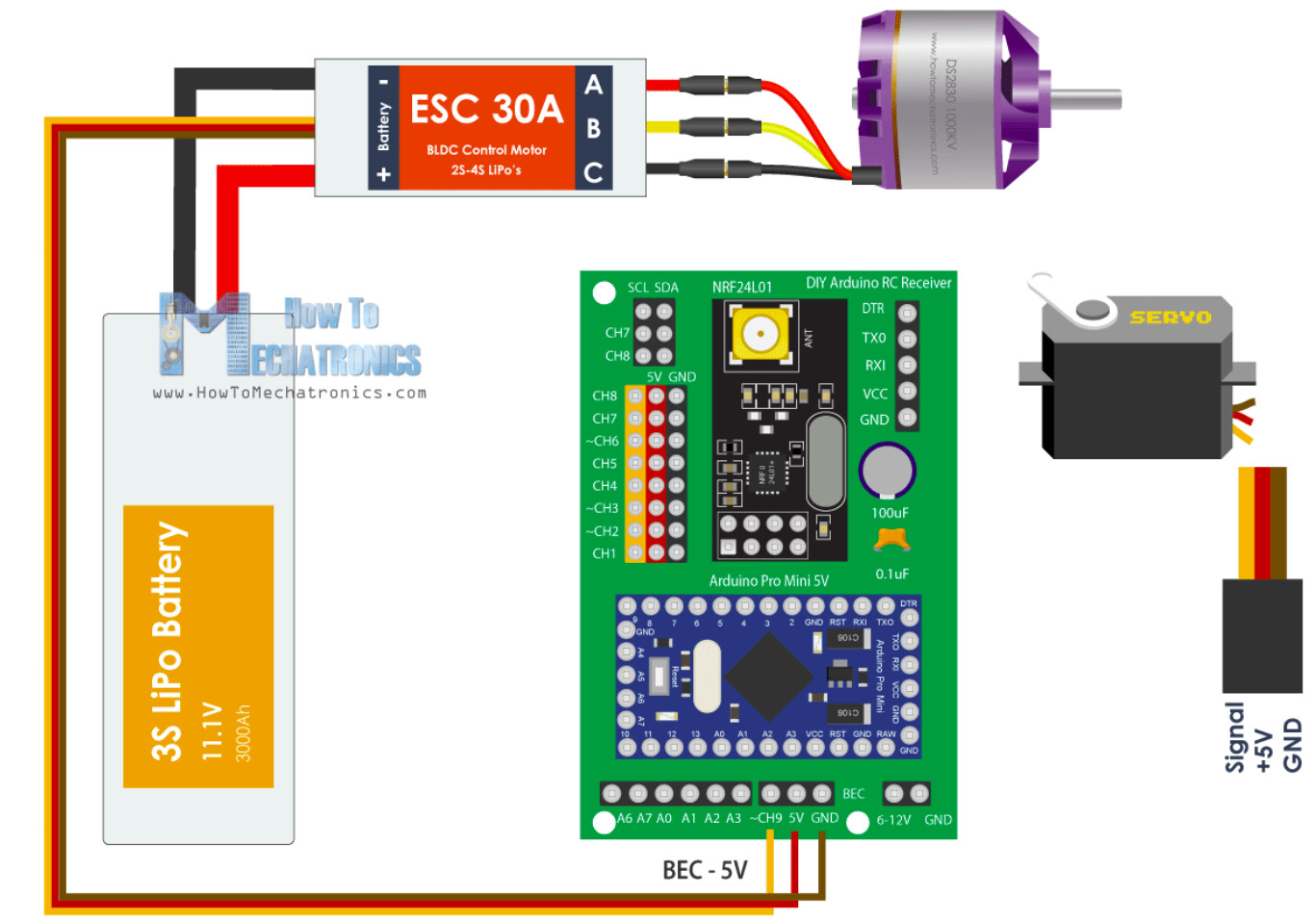
FOR THE RECEIVER :-
Circuit and the code provided were used directly without any changes.
Code of Receiver :-
/*
  DIY RC Receiver - Servos and Brushless motors control
  by Dejan, www.HowToMechatronics.com
  Library: TMRh20/RF24, https://github.com/tmrh20/RF24/
*/
#include <SPI.h>
#include <nRF24L01.h>
#include <RF24.h>
#include <Servo.h>

RF24 radio(3, 2);   // nRF24L01 (CE, CSN)
const byte address[6] = "00001";
unsigned long lastReceiveTime = 0;
unsigned long currentTime = 0;
Servo esc;  // create servo object to control the ESC
Servo servo1;
Servo servo2;
int escValue, servo1Value, servo2Value;
// Max size of this struct is 32 bytes - NRF24L01 buffer limit
struct Data_Package {
  byte j1PotX;
  byte j1PotY;
  byte j1Button;
  byte j2PotX;
  byte j2PotY;
  byte j2Button;
  byte pot1;
  byte pot2;
  byte tSwitch1;
  byte tSwitch2;
  byte button1;
  byte button2;
  byte button3;
  byte button4;
};
Data_Package data; //Create a variable with the above structure
void setup() {
  Serial.begin(9600);
  radio.begin();
  radio.openReadingPipe(0, address);
  radio.setAutoAck(false);
  radio.setDataRate(RF24_250KBPS);
  radio.setPALevel(RF24_PA_LOW);
  radio.startListening(); //  Set the module as receiver
  resetData();
  esc.attach(10);   // Arduino digital pin D10 - CH9 on PCB board
  servo1.attach(4); // D4 - CH1
  servo2.attach(5); // D5 - CH2
}
void loop() {

  // Check whether we keep receving data, or we have a connection between the two modules
  currentTime = millis();
  if ( currentTime - lastReceiveTime > 1000 ) { // If current time is more then 1 second since we have recived the last data, that means we have lost connection
    resetData(); // If connection is lost, reset the data. It prevents unwanted behavior, for example if a drone jas a throttle up, if we lose connection it can keep flying away if we dont reset the function
  }

  // Check whether there is data to be received
  if (radio.available()) {
    radio.read(&data, sizeof(Data_Package)); // Read the whole data and store it into the 'data' structure
    lastReceiveTime = millis(); // At this moment we have received the data
  }

  // Controlling servos
  servo1Value = map(data.j2PotX, 0, 255, 0, 180); // Map the receiving value form 0 to 255 to 0 to 180(degrees), values used for controlling servos
  servo2Value = map(data.j2PotY, 0, 255, 0, 180);
  servo1.write(servo1Value);
  servo2.write(servo2Value);

  // Controlling brushless motor with ESC
  escValue = map(data.j1PotY, 127, 255, 1000, 2000); // Map the receiving value form 127 to 255 to  1000 to 2000, values used for controlling ESCs
  esc.writeMicroseconds(escValue); // Send the PWM control singal to the ESC

}
void resetData() {
  // Reset the values when there is no radio connection - Set initial default values
  data.j1PotX = 127;
  data.j1PotY = 127;
  data.j2PotX = 127;
  data.j2PotY = 127;
  data.j1Button = 1;
  data.j2Button = 1;
  data.pot1 = 1;
  data.pot2 = 1;
  data.tSwitch1 = 1;
  data.tSwitch2 = 1;
  data.button1 = 1;
  data.button2 = 1;
  data.button3 = 1;
  data.button4 = 1;
}
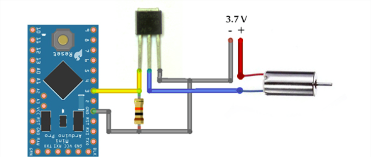
We have tried above transmitter and receiver circuit with servo motor. The servo motor operation is working successfully. However, when we connected coreless motor, it didn't work. We did this trial with the following MOSFET/transistor.
- IRFZ44N
- IRF9540N
- TIP122 (Transistor)