Hi everyone.
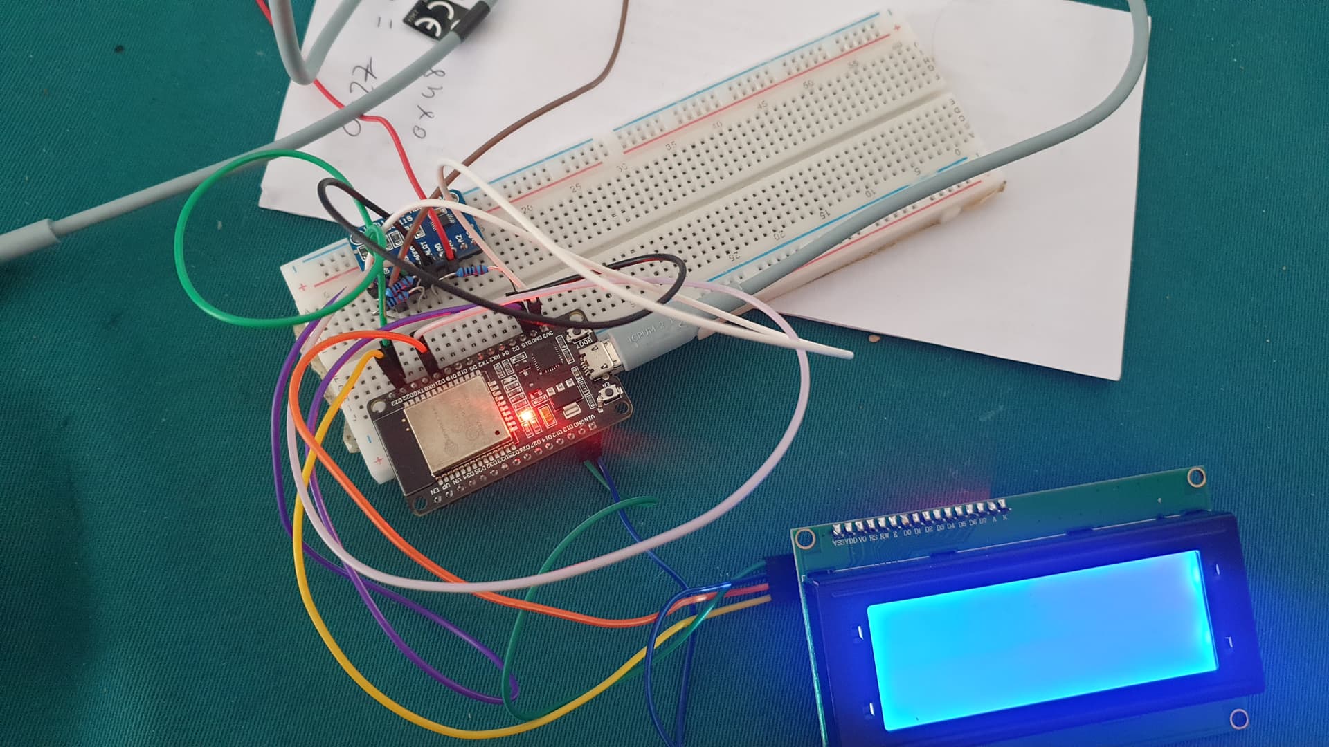
I did a montage with esp32 + ADS1115 and liquid crystal as this exemple from thissite :

However my display stills freezen. Datas are not. However i know that the adress stills reconized : 0x24 for display and 0x48 for ads. And Yes, i see inside serial monitor
Also as mentioned by this site i used :
his design adheres to the standard connection protocol for the ADS1115 chip. It features 10K ohm pull-up resistors on both the I2C and Alert pins, as well as a 1uF capacitor situated between the VDD and GND pins, functioning as a decoupling capacitor.
Could you tell me if the issue is that ads 1115 takes all the memory? is that as i used the same pins for two differents devices, there's a conflict? If you could tell me the solutions ![]() thanks
thanks
The code here :
#include <Adafruit_ADS1X15.h>
#include <LiquidCrystal_I2C.h>
LiquidCrystal_I2C lcd(0x27, 16, 2);
Adafruit_ADS1115 ads;  /* Use this for the 16-bit version */
//Adafruit_ADS1015 ads;     /* Use this for the 12-bit version */

void setup(void)
{
  Serial.begin(115200);

  Serial.println("Getting single-ended readings from AIN0..3");
  Serial.println("ADC Range: +/- 6.144V (1 bit = 3mV/ADS1015, 0.1875mV/ADS1115)");

  // The ADC input range (or gain) can be changed via the following
  // functions, but be careful never to exceed VDD +0.3V max, or to
  // exceed the upper and lower limits if you adjust the input range!
  // Setting these values incorrectly may destroy your ADC!
  //                                                                ADS1015   ADS1115
  //                                                                -------  -------
  // ads.setGain(GAIN_TWOTHIRDS);  // 2/3x gain +/- 6.144V  1 bit = 3mV      0.1875mV (default)
  // ads.setGain(GAIN_ONE);        // 1x gain   +/- 4.096V  1 bit = 2mV      0.125mV
  //ads.setGain(GAIN_TWO);        // 2x gain   +/- 2.048V  1 bit = 1mV      0.0625mV
  // ads.setGain(GAIN_FOUR);       // 4x gain   +/- 1.024V  1 bit = 0.5mV    0.03125mV
  // ads.setGain(GAIN_EIGHT);      // 8x gain   +/- 0.512V  1 bit = 0.25mV   0.015625mV
  // ads.setGain(GAIN_SIXTEEN);    // 16x gain  +/- 0.256V  1 bit = 0.125mV  0.0078125mV

  lcd.init();
  lcd.backlight();
  if (!ads.begin())
  {
    Serial.println("Failed to initialize ADS.");
    while (1);
  }
}

void loop(void)
{
  int16_t adc0, adc1, adc2, adc3;
  float volts0, volts1, volts2, volts3;

  adc0 = ads.readADC_SingleEnded(0);
  adc1 = ads.readADC_SingleEnded(1);
  adc2 = ads.readADC_SingleEnded(2);
  adc3 = ads.readADC_SingleEnded(3);

  volts0 = ads.computeVolts(adc0);
  volts1 = ads.computeVolts(adc1);
  volts2 = ads.computeVolts(adc2);
  volts3 = ads.computeVolts(adc3);

  Serial.println("-----------------------------------------------------------");
  Serial.print("AIN0: "); Serial.print(adc0); Serial.print("  "); Serial.print(volts0); Serial.println("V");
  Serial.print("AIN1: "); Serial.print(adc1); Serial.print("  "); Serial.print(volts1); Serial.println("V");
  Serial.print("AIN2: "); Serial.print(adc2); Serial.print("  "); Serial.print(volts2); Serial.println("V");
  Serial.print("AIN3: "); Serial.print(adc3); Serial.print("  "); Serial.print(volts3); Serial.println("V");

  lcd.clear();
  lcd.setCursor(0, 0);
  lcd.print("ADC0:");
  lcd.print(adc0);
  lcd.print("  ");
  lcd.print(volts0);
  lcd.print("V");

  lcd.setCursor(0, 1);
  lcd.print("ADC1:");
  lcd.print(adc1);
  lcd.print("  ");
  lcd.print(volts1);
  lcd.print("V");
  delay(1000);
}