Issues with controlling led light strip with MOSFET

Hi guys, I'm doing my first project that uses Arduino to control a 5050RGB LED light strip with MOSFET.
Here is the code:


#define ITERATION 15
#define DELAY 2
#define FAULT_DELAY 100
#define MAX_BVAL 255
#define rPin 3
#define gPin 5
#define bPin 6

int NumberSounds = 0;
int SoundPin = 2;
int RawValue = 0;
int NumberClaps = 0;
int LightOn = 0;
unsigned long SoundDetectedTime = 0;
unsigned long PreviousSoundDetectedTime = 0;
int UniqueClapMinTime = 100;
int LEDPin = 13;
unsigned long PreviousClapTime = 0;
unsigned long CurrentClapTime = 0;
unsigned long MaxTimeBetweenClaps = 2000;
unsigned long lastMillisec = 0;
unsigned long current_time = 0;
unsigned long elapsed_time = 0;
int sample = 0;

long totalValue = 0;
int count = 0;

int counter = 1;
int aState;
int aLastState;

int rBr = 0;
int bBr = 0;
int gBr = 0;

boolean state = false;
int lastClap = 2;

void setup()
{
    // put your setup code here, to run once:
    Serial.begin(9600);
    pinMode(rPin, OUTPUT);
    pinMode(gPin, OUTPUT);
    pinMode(bPin, OUTPUT);
    pinMode(SoundPin, INPUT);
    pinMode(LEDPin, OUTPUT);
}

int IsSoundPartOfUniqueClap()
{
    int result = 0;
    unsigned long ElapsedTime =
        SoundDetectedTime -
        PreviousSoundDetectedTime;
    if (ElapsedTime >= UniqueClapMinTime)
    {
        result = 1;
    }
    return result;
}

int CheckTurnOnOffLight()
{
    int result = 0;
    unsigned long ElapsedTime =
        CurrentClapTime - PreviousClapTime;
    if (ElapsedTime <= MaxTimeBetweenClaps)
    {
        if (NumberClaps == 2)
        {
            result = 1;
            NumberClaps = 0;
        }
    }
    else
    {
        NumberClaps = 1;
    }
    return result;
}

void off()
{
    setRed(0);
    setGreen(0);
    setBlue(0);
}

void setRed(int br)
{

    int accu = br > rBr ? 1 : -1;
    for (rBr; rBr != br; rBr += accu)
    {
        analogWrite(rPin, rBr);
        delay(DELAY);
    }
}

void setGreen(int br)
{

    int accu = br > gBr ? 1 : -1;
    for (gBr; gBr != br; gBr += accu)
    {
        analogWrite(gPin, gBr);
        delay(DELAY);
    }
}

void setBlue(int br)
{

    int accu = br > bBr ? 1 : -1;
    for (bBr; bBr != br; bBr += accu)
    {
        analogWrite(bPin, bBr);
        delay(DELAY);
    }
}

void hsv(int value)
{
    if (value <= 60)
    {
        setRed(255);
        setBlue(0);
        setGreen(map(value, 0, 60, 0, 255));
    }
    else if (value > 60 && value <= 120)
    {
        setGreen(255);
        setBlue(0);
        setRed(255 - map(value, 60, 120, 0, 255));
    }
    else if (value > 120 && value <= 180)
    {
        setRed(0);
        setGreen(255);
        setBlue(map(value, 120, 180, 0, 255));
    }
    else if (value > 180 && value <= 240)
    {
        setRed(0);
        setBlue(255);
        setGreen(255 - map(value, 180, 240, 0, 255));
    }
    else if (value > 240 && value <= 300)
    {
        setBlue(255);
        setGreen(0);
        setRed(map(value, 240, 300, 0, 255));
    }
    else if (value > 300 && value <= 360)
    {
        setRed(255);
        setGreen(0);
        setBlue(255 - map(value, 300, 360, 0, 255));
    }
}

void loop()
{
    RawValue = digitalRead(SoundPin);
    if (RawValue == 0)
    {
        NumberSounds++;

        // Process raw data for claps
        PreviousSoundDetectedTime =
            SoundDetectedTime;
        SoundDetectedTime = millis();
        if (IsSoundPartOfUniqueClap())
        {
            NumberClaps++;

            // Update Clap Times
            PreviousClapTime =
                CurrentClapTime;
            CurrentClapTime = millis();

            // Turn Light ON/OFF as needed
            if (CheckTurnOnOffLight())
            {
                LightOn = ~LightOn;
                if (LightOn)
                {
                    state = true;
                }
                else
                {
                    state = false;
                }
            }
        }
    }

    if (state)
    {
        int sensorValue = analogRead(A0);
        totalValue += sensorValue;
        if (count++ == ITERATION)
        {
            hsv(map(totalValue / ITERATION, 0, 1023, 0, 255));
            totalValue = 0;
            count = 1;
        }
        digitalWrite(13, HIGH);
    }
    else
    {
        off();
        digitalWrite(13, LOW);
    }
}

I'm following this youtube video for guidance and the led wiring part is identical.
LED video
This is the schematic I created myself:

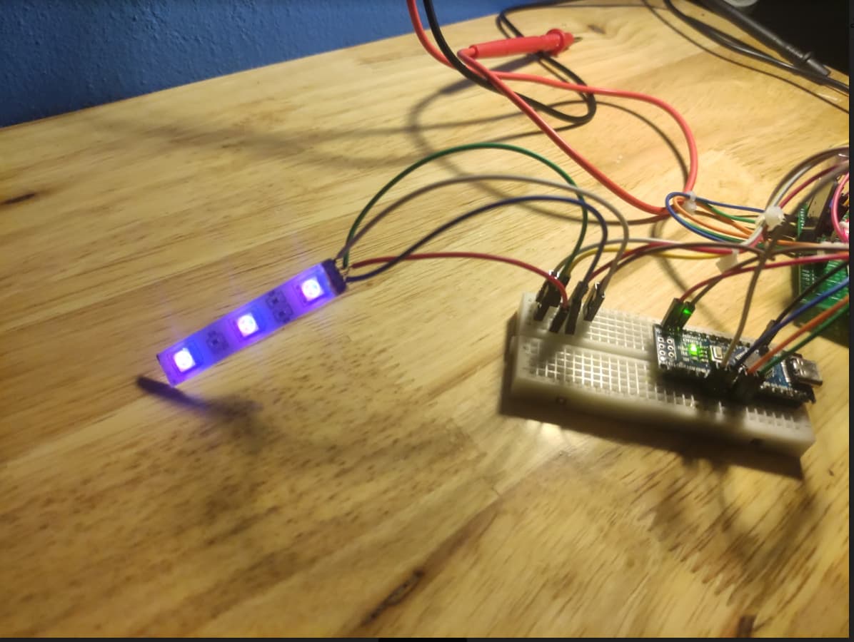
I've tested it on a breadboard and It works fine, after that, I make a board that looks like this:


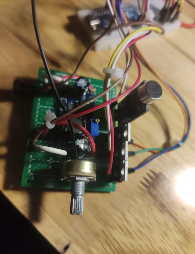
But when I power it on, The light should be off completely but it still shows a dim light:


I'm pretty sure all my wirings are done correctly and tested connectivity.
and also, the middle MOTFES seems to not work right because when I give 4.0 voltage to the gate, the drain only gets around 5v.
Wonder why is this happening, could anyone help me, please?

If you are sure in your connection, please answer the question:
What are "analog in" in the scheme and why do you control mosfets from it if are "inputs"?

what is this? fade?
What is the point of this code?

Your for loop runs and stops almost immediately, your fade loop is completely useless.
You easily can replace this code by just one line:

 void setGreen(int br)
{
        analogWrite(gPin, br);
}

Hi;
There are errors in your schematic.
In the sound module the + is shorted to GND;

And DO is shorted to + or GND.
Check if the PCB is correct.

Those FETs you used are not logic level FETs and do not achieve full switch on until you give them a 10V gate signal. It looks like the component spread you get with all components is allowing you to get some functionality with the limited gate voltage you have, but it is not very good functionality.

You need to use a logic level FET that will switch on fully at 5V. If you look at the data sheet you will see a parameter for Rsd(on) which is the resistance between the source and the drain when it is on. In the conditions column you will see what gate voltage this was tested at. You will see for your FET this condition was Vgs (voltage between gate and source) as 10V. This is where you have to look on a data sheet to see if it is suitable for using with your Arduino.

Do not be fooled by the threshold voltage, this is the voltage below which there is no conduction. Or in other words the voltage where the FET just begins to start conducting.

Nice but some of the labelling is wrong. The connections to the gate of the FET is labelled Analog In, where it is the Analogue Out pin, which on an Arduino actually a PWM output signal.

Sorry, I'm using the IRFZ4N Datasheet


From what I can see, this is a logic-level FET. I'm using easy EDA and just use whatever I found there, Sorry if this confuses you.
And for the "Analog in" I meant The PWM output from Arduino. I'm using a breadboard Arduino for this project so It's my way to say that it connects to the Arduino PWM output. The drain should be connected to the led's red, green, and blue pins.

Sorry, It was totally my bad and it was not a PCB, just a though hole board that I soldered myself so I checked all the sorting and the sound sensor works.

Right, I forgot to add some delay there, sorry for the nuisance.

The "analog in" is my way to say it's the PWM output from the Arduino board. It's to control the flow from gate to source.

PWM is a digital signal.

Oh, right...

What makes you say that after my explanation of how you can tell if it is a logic level FET?
It is very clearly not.

It might be but it is not the way everyone else in the world defines inputs and outputs. It lessens confusion if you use words in the way that are universally accepted.

Guys, I might have found out why the light does not turn off entirely when I use analogWrite(pin, 0). According to this page The page, so I've changed the code fragment from this:

void setRed(int br)
{

    int accu = br > rBr ? 1 : -1;
    for (rBr; rBr != br; rBr += accu)
    {
        analogWrite(rPin, rBr);
        delay(DELAY);
    }
}

void setGreen(int br)
{

    int accu = br > gBr ? 1 : -1;
    for (gBr; gBr != br; gBr += accu)
    {
        analogWrite(gPin, gBr);
        delay(DELAY);
    }
}

void setBlue(int br)
{

    int accu = br > bBr ? 1 : -1;
    for (bBr; bBr != br; bBr += accu)
    {
        analogWrite(bPin, bBr);
        delay(DELAY);
    }
}

To this:

void setRed(int br)
{
    if(br == 0)
      digitalWrite(rPin, 0);
    int accu = br > rBr ? 1 : -1;
    for (rBr; rBr != br; rBr += accu)
    {
        analogWrite(rPin, rBr);
        delay(DELAY);
    }
}

void setGreen(int br)
{
    if(br == 0)
      digitalWrite(g Pin, 0);
    int accu = br > gBr ? 1 : -1;
    for (gBr; gBr != br; gBr += accu)
    {
        analogWrite(gPin, gBr);
        delay(DELAY);
    }
}

void setBlue(int br)
{
    if(br == 0)
      digitalWrite(bPin, 0);
    int accu = br > bBr ? 1 : -1;
    for (bBr; bBr != br; bBr += accu)
    {
        analogWrite(bPin, bBr);
        delay(DELAY);
    }
}

This will use digitalWrite instead of analogWrite when the value needed is 0 which turns the LED off completely. So glad this worked, but when I run this with Arduino nano, it gets so hot I can't even touch it. I re-wired the board to a breadboard that looks like this:


All the functions work almost fine but the overheating keeps worrying me. I'm using the step-down converter to power the POT, sound sensor, and Arduino.
Can you guys help me find out what the problem is?

Did you see on the datasheet that Vgsth (the voltage where the MOSFET barely cracks on) could be as high as 4 volts? Do you know that if you are powering Nano from USB, the output pin voltage is only about 4.7 volts? You have the wrong MOSFET.

Well, I noticed it and change the MOSFET to the H1061 transistor. Things now work but there is now overheating problem with the Arduino. I discovered the atmega328p does not heat up when the led is not turned on, maybe the problem is the analogWrite function? The microcontroller might be heating up because Its outputting 3 PWM signal all the time.

Transistors dissipate more heat than a proper logic level FET. Also what value is the base resistor? If that is too low it will draw too much current from the Arduino and heat it up. Your base resistor should be no lower than 200R.

No surprise here.

No.

No.

For god sake man get a proper logic level FET and have done. After all, you posted here for advice. You got advice from serval people that you have the wrong type of FET. So why are you not paying any attention to this?

1 Like

Alright, let me first apologize for being ignorant. I am currently very new to this hobby and still learning a lot. The only FET I got is the Z44N. I ordered some IRF540 from china and it should take about a month to arrive. So using a transistor is the best thing I can do right now.

Thank you for the advice, I was using the resistors Incorrectly as the current will just go straight through without any resistance. I re-wired the board and all the problems are gone. I didn't know the transistor's thermal resistance is that much more than a logic level FET.

In electronics the term thermal resistance refers to the flow of heat between two places. For example from the chip to the component's surface or from component's surface to a heat sink, or from heat sink to ambient. It is measured in units of degrees centigrade per watt.

It has nothing to do with the heat generated by a bipolar transistor or a FET.

With a transistor when it is saturated, or fully on as it is called, there is a saturation voltage between emitter and collector called Vsat. This can be up to 2V for a power transistor, and is never less that 0.7V for any silicon transistor. So the heat it generates in watts can be found by the current times the Vsat.

For an FET there is no fixed Vsat but there is in effect one caused by the current flowing through the turn on resistance of the FET the Rsd, resistance between source and drain. This is why this figure is important and in general produces a very much smaller amount of heat for the same current flowing through it. However this Rsd is dependant on the gate voltage. So if you get a FET and you have not got enough gate voltage to fully turn it on, this Rds will be much higher that it could be and so it will generate much more heat than it should be.

The important figure is not the threshold voltage, it is the Rds minimum value. In the date sheet this has a condition against the parameter of a gate voltage and a current.

A logic level FET will have this condition of a gate voltage of about 4.7V. None of the two FETs you have mentioned are logic level FETs

Anyway glad you got it working.

This is not true! Saturation voltage may be nearly zero if the Collector current is low and Base current is high (i.e. when driving a capacitive load such as a MOSFET Gate).

Also it is true MOSFETs used by OP are not a good choice. But this surely cannot cause the observed behavior! It may be problem to turn them on; turning them off should be easier than with a logic level MOSFET.

how about a pulldown resistor to turn it off, say 1kohm gate to ground... treat the gate like a small capacitor, if it is not discharged fet stays conducting, or a hex buffer, or a fet opto driver like tlp251,
or a pnp-npn pair of small bjts to pull the gate up and down, there are other solutions too...

bottom line is you need the gate above the treshold voltage for turn on, and you need it grounded for turn off, maybe arduino is enough to directly drive small fets, but I wouldn't stress it if i dont need to... switching frequency plays a big role in gate current/losses too, and in larger fets the gate capacitance can even resonate with inductance in the wires if it turns on too fast, and make the fet turn on and off repetedly until it stabilises, that can leed to overheat and more unwanted transients if the load is inductive, so you need a gate resistor then.
hope this helps in the future when you need to drive fets or igbts

1 Like