I am currently working on a project using the SCT013 current sensor connected to an ESP32. I am encountering an issue where the sensor displays current readings even when it is not connected to any load. I would like to seek your guidance on resolving this problem.
Here are the details of my setup:
#include "EmonLib.h"   // Library for SCT013 reading

EnergyMonitor SCT013;   // Create an EnergyMonitor object for the sensor

// Pin and variable definitions
int pinSCT = 34;        // Pin for the sensor signal
int voltage = 220;      // Voltage value (220V)
double power;           // Variable for calculating power

void setup() {
    Serial.begin(115200);  // Initialize serial monitor for debugging
    SCT013.current(pinSCT, 0.5);  // Configure the SCT013 sensor on the pin and calibrate for 30A
}

void loop() {
    double Irms = SCT013.calcIrms(1480);  // Calculate the RMS current value with 1480 samples

    // Check if the reading is significant
    if (Irms < 0.05) {
        Irms = 0;  // Ignore readings below 0.05A
    }

    power = Irms * voltage;  // Calculate power based on current and voltage

    // Display values on serial monitor
    Serial.print("Current (Irms): ");
    Serial.print(Irms, 3);    // Show current in Amperes
    Serial.print(" A\tPower: ");
    Serial.print(power, 2);  // Show power in Watts
    Serial.println(" W");

    delay(1000);  // Interval of 1 second between readings
}
Observed Values:
Current readings (Irms) fluctuate between 0.000 A and values such as 0.102 A, even when no load is connected.
Questions:
Interference and Noise: Is it common for the SCT013 sensor to pick up noise when not connected to a load? What are the best practices for minimizing interference in this type of setup?
Calibration: I am using a calibration factor of 0.5. How can I verify that this value is appropriate for my specific SCT013 sensor?
Code Improvements: Are there any code adjustments you would recommend to further filter out these erroneous readings?
Testing with Load: Should I test the sensor with a known load to ensure that it is functioning correctly, and if so, what type of load would you suggest?
Any help or insights would be greatly appreciated! Thank you in advance for your support!
According to the web page theoretical CT calibration, the 'calibration factor' as used by openenergymonitor is defined as the current transformer turns ratio / burden resistance.
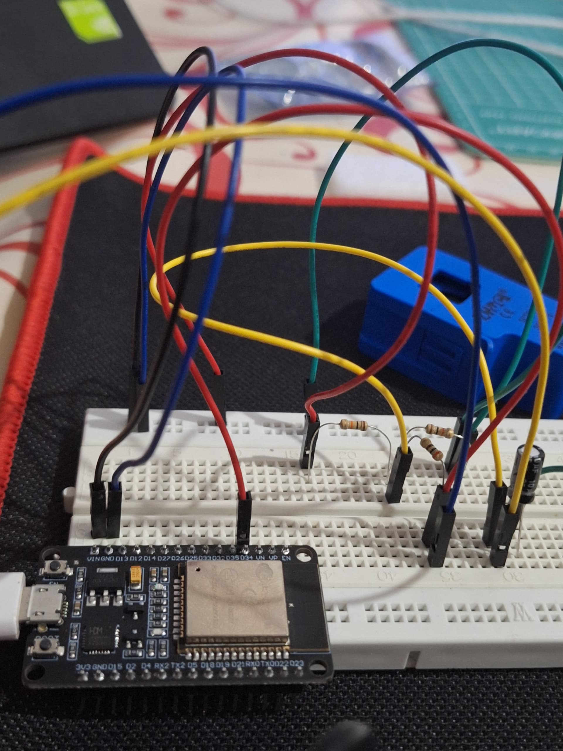
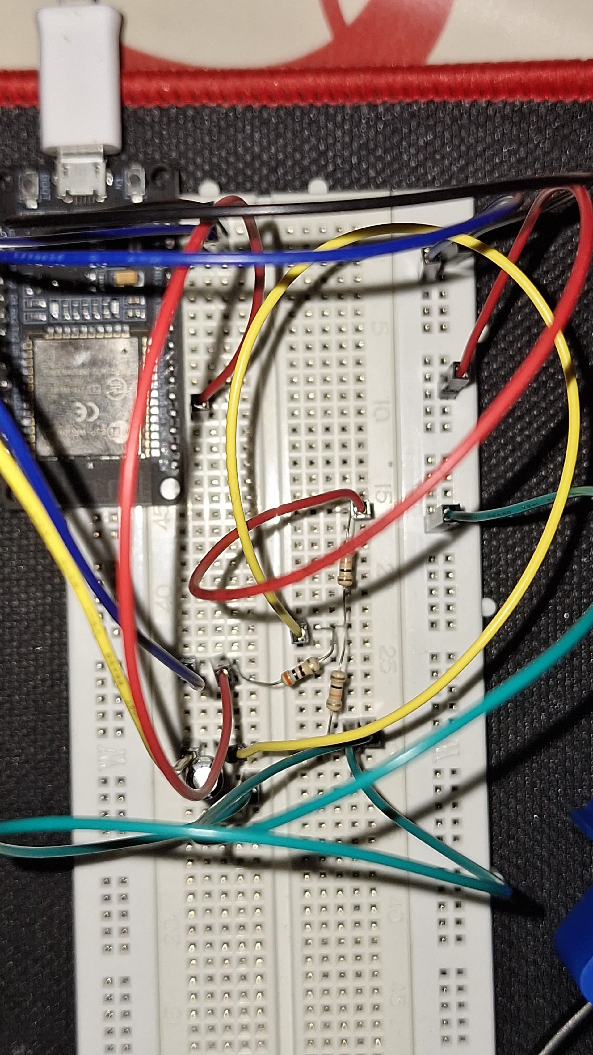
Thank you for the explanation about the calibration factor! To clarify, I'm using two 10 kΩ (5%) resistors and one 300 Ω (5%) resistor in my circuit. My CT013 sensor is rated for 30A, and I'm measuring currents in that range.
Currently, I'm not using a 4000 Ω burden resistor, but rather the 300 Ω one. Considering this, could you help me understand what the appropriate calibration factor would be? I appreciate your assistance!
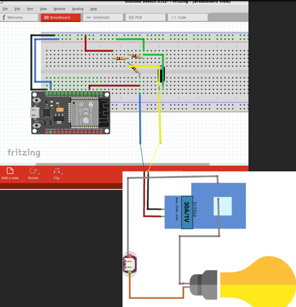
10k:10k is the voltage divider that provides a 1.65volt mid-voltage offset for the 3.3volt-logic A/D. The tap should have a cap to ground (which you have).
But why a 300 ohm resistor...
SCT013 is a family of CT, so what exactly is written on the CT.
If it has 1volt below the 30A, then it already has a built-in burden resistor.
Only the mA versions don't have a built-in burden resistor.
The 1volt version (2.83volt peak/peak) is a good match for you 3.3volt-logic ESP32.
Leo..
Even though your current transformer is rated at 30A, you won't be able to measure currents up to 30A using that 300Ω burden resistor.
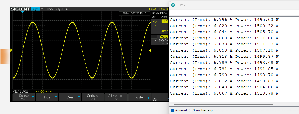
To demonstrate this I have used a function generator to simulate the output of a current sensor.
I don't have an ESP32 board, so I used an Arduino Uno R3 for the demonstration.
For a 50Hz,1V RMS sine wave, and the calibration factor set to 6.667, I got the following results:
For a 1V RMS signal the 'simulated' current measurement is equal to the calibration factor. (within the limits of experimental error)
The peak to peak voltage is 2.828V - This is close to the maximum voltage that you could measure using a 3.3V ESP32.
So although your current transformer may be rated at 30V, you will only be able to measure say 6-7A using a 300Ω burden resistor.
If you wanted to measure 30A then you would need a smaller burden resistance, around 300Ω/5 = 60Ω. (and a new calibration factor should be calculated).
The original question was noise with zero current through the sensor.
Connecting the voltage divider to V-in (wrong) could have caused (some off) that.
(post#2)
So what is the result after connecting the voltage divider to 3.3volt.
Leo..
All sensors and the Arduino ADC exhibit random noise, and loops of wire work as antennas, picking up signals from the nearby AC wiring, appliances and overhead lighting.
I have all the materials I need for the project, but could the problem be in the way I’m assembling them?
What would be the correct way? Could you kindly help me with that?