Hey,
I'm creating a remote control tank, my issue lies within the controller itself
my joysticks don't seem to be reading properly as they will (both) jump from their highest value to the lowest and then back up
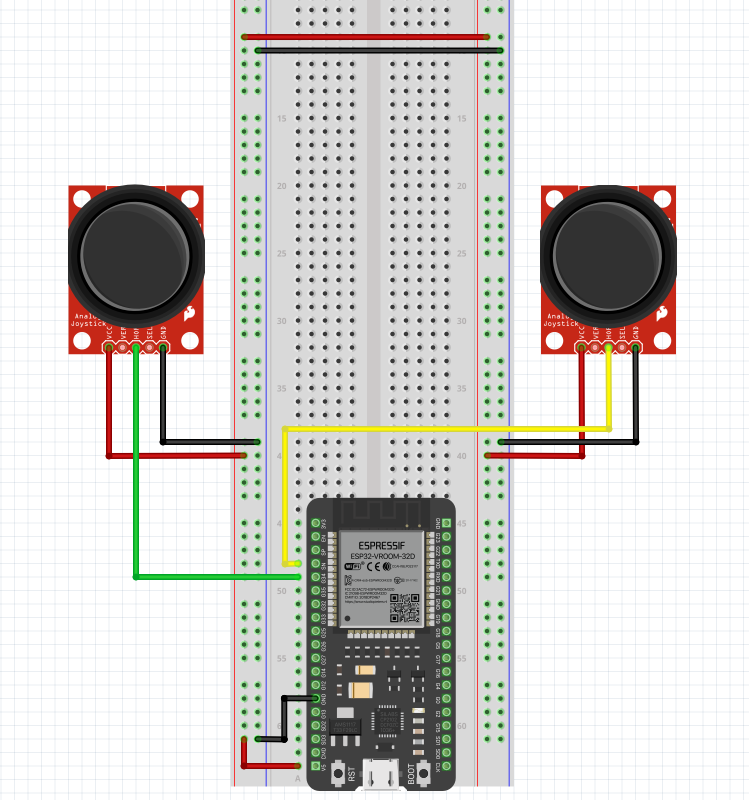
my breadboard setup
my code
const int leftJoy = A7;
//const int rightJoy = A6;

int leftVal = 0;
//int rightVal = 0;

void setup() {
  Serial.begin(115200);
  pinMode(leftJoy, INPUT);
  //pinMode(rightJoy, INPUT);

}

void loop() {
  leftVal = analogRead(leftJoy);
  //rightVal = analogRead(rightJoy);
  Serial.print("left: ");
  Serial.print(leftVal);
  //Serial.print(" | right: ");
  //Serial.print(rightVal);
  Serial.println();
  delay(100);

}
any advice would be greatly appreciated
Maybe check the wiring: you may have interchanged 2 wires on each joystick.
An electrical matter. Posting schematics is mandatory. Else helpers might send You hundreds of guesses.....
You forgot to tell what controller You use. Does it have any A7, does that pin provide ADC?
agent_pup:
my breadboard setup
Not useful for detailed replies. Schematics are.
See this for general help on using ESP32 analog inputs.
Just because the joystick board has a pin labelled 5V, does not mean this is correct for devices that use 3.3V logic levels. The ESP32 uses 3.3V so be sure to connect the red wire to 3.3V. The ESP32 does not have labels on the pins it is hard tell which is the correct pin.
here is my schematic
from what i have read on https://www.electronicshub.org/esp32-adc-tutorial/
i will see if this works, i didn't realise that the joysticks could use 3.3v logic
Fritzings are useless for precision matters. No engineer needs to see the physical shape of devices. The logic pins etc. are interesting.
You're not the first member forgetting to tell what controller You use. Anyway, pots should be connected between Vcc and Gnd. 5.0 or 3,3 volt Vcc, no difference.
Are your breadboard power and ground rails continuous? Sometimes they aren't connected at the center of the board.
If that's the case, the pins could be floating.
my power and ground rails are continuous, the only reason i have the 2 wires at the top are to transfer power to the other side
Those 2 bob joysticks have a reputation of being unreliable, same for breadboard connections and jumper cables, however.......
Do you get a steady increasing or/and decreasing voltage measurement from centre pin to ground on each pot as they are moved ?
I suppose I should ask first, do you have a test meter??
the resistance on the pots seems to be on a linear scale
That may be but I asked about the voltage.
Probably best measured at the ground and analog input pins on the uC, that way we can see what the uC sees.
Do a test for each input and show the results here.
bluejets:
centre pin to ground
thanks for clarifying (now I understand what you were asking of me)
I found I had a bad connection with my breadboard and was not getting stable power to the joysticks
it appears that it is now working by changing the location of the physical pins
Completely unrelated to your question but still useful: