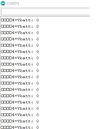
Hi guys!, I am having a trouble display the exact values for my wind direction sensor. Here is my connections:
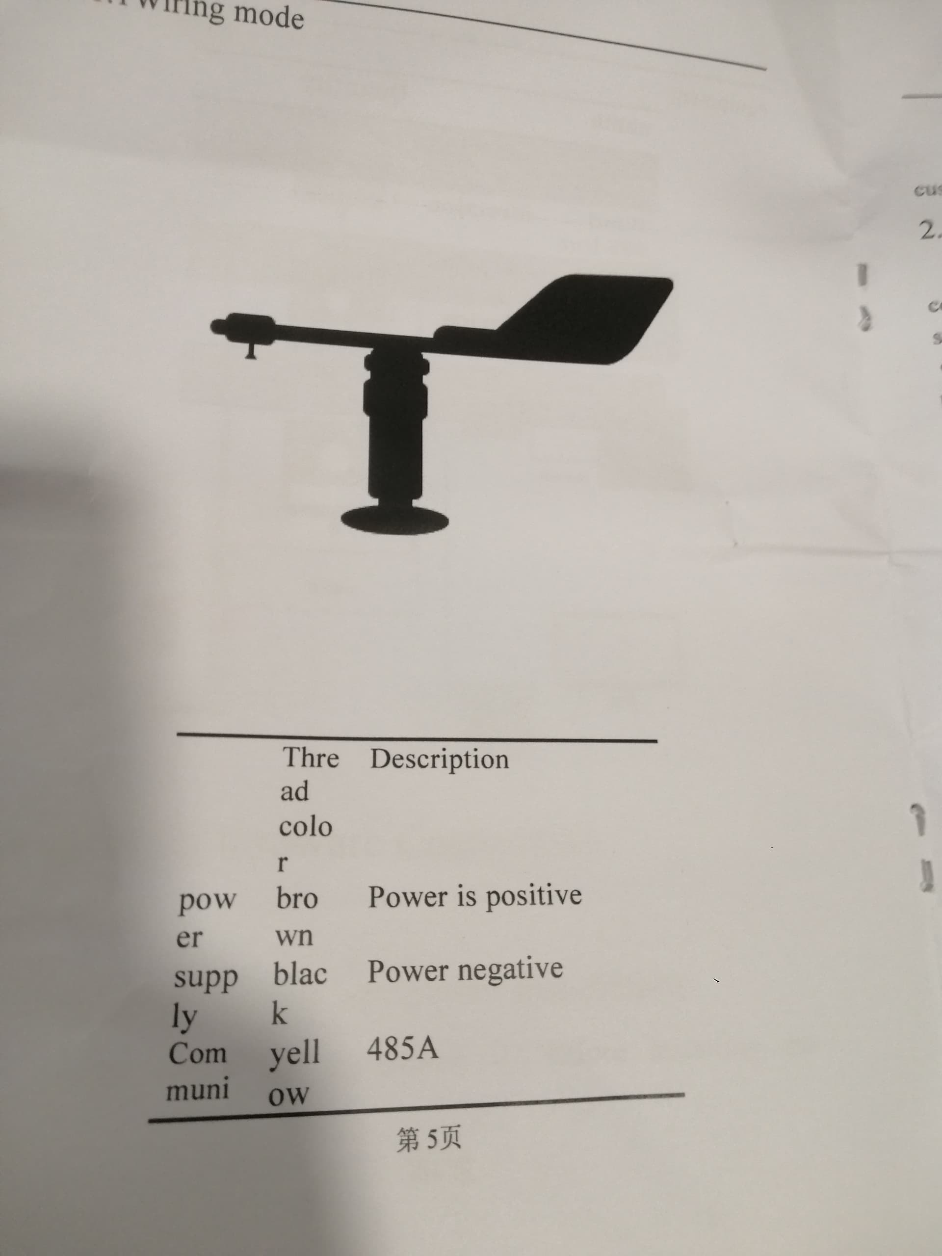
Wind Direction Sensor
Black Wire to 12-24v Power Supply
Brown Wire to 12-24v Power Supply
Yellow Wire to A green terminal block
Blue Wire to B green terminal block
MAX485 ttl to RS485 Module to Arduino Mega
VCC to VCC
GND to GND
DI to TX0
DE to 4
RE to 5
RO to RX0
It's not very clever to run the Modbus serial on the same interface you use to communicate the values to the PC (and for debugging). The Mega has 4 (!) hardware serial interface so I recommend to use another one than the PC connection (p.e. Serial1 and TX1/RX1).
Post a link to the manual of your wind direction sensor. Many Modbus sensors use a parity bit to further enhance the reliability of the Modbus connection. If you do this wrong you won't get a response from the sensor.
wiring---
Wind Direction Sensor
Black Wire to 12-24v Power Supply
Brown Wire to 12-24v Power Supply
Yellow Wire to A green terminal block
Blue Wire to B green terminal block
MAX485 ttl to RS485 Module to Arduino Mega
VCC to VCC
GND to GND
DI to TX1
DE to 4
RE to 5
RO to RX1
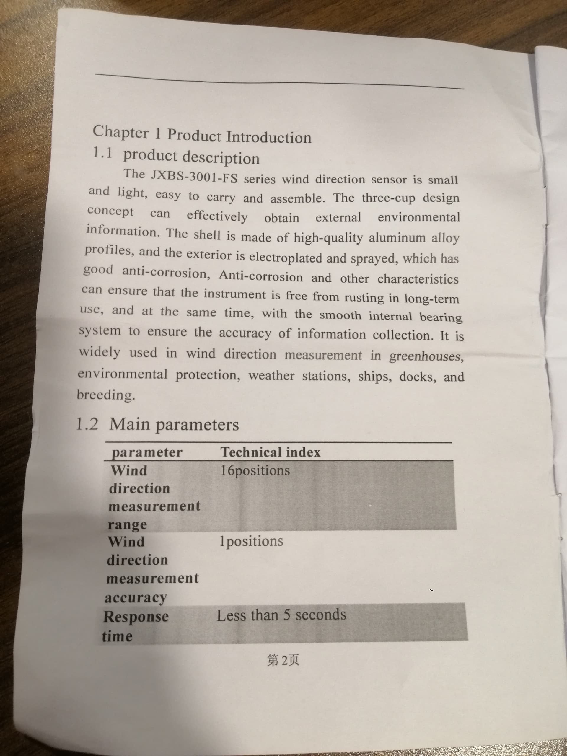
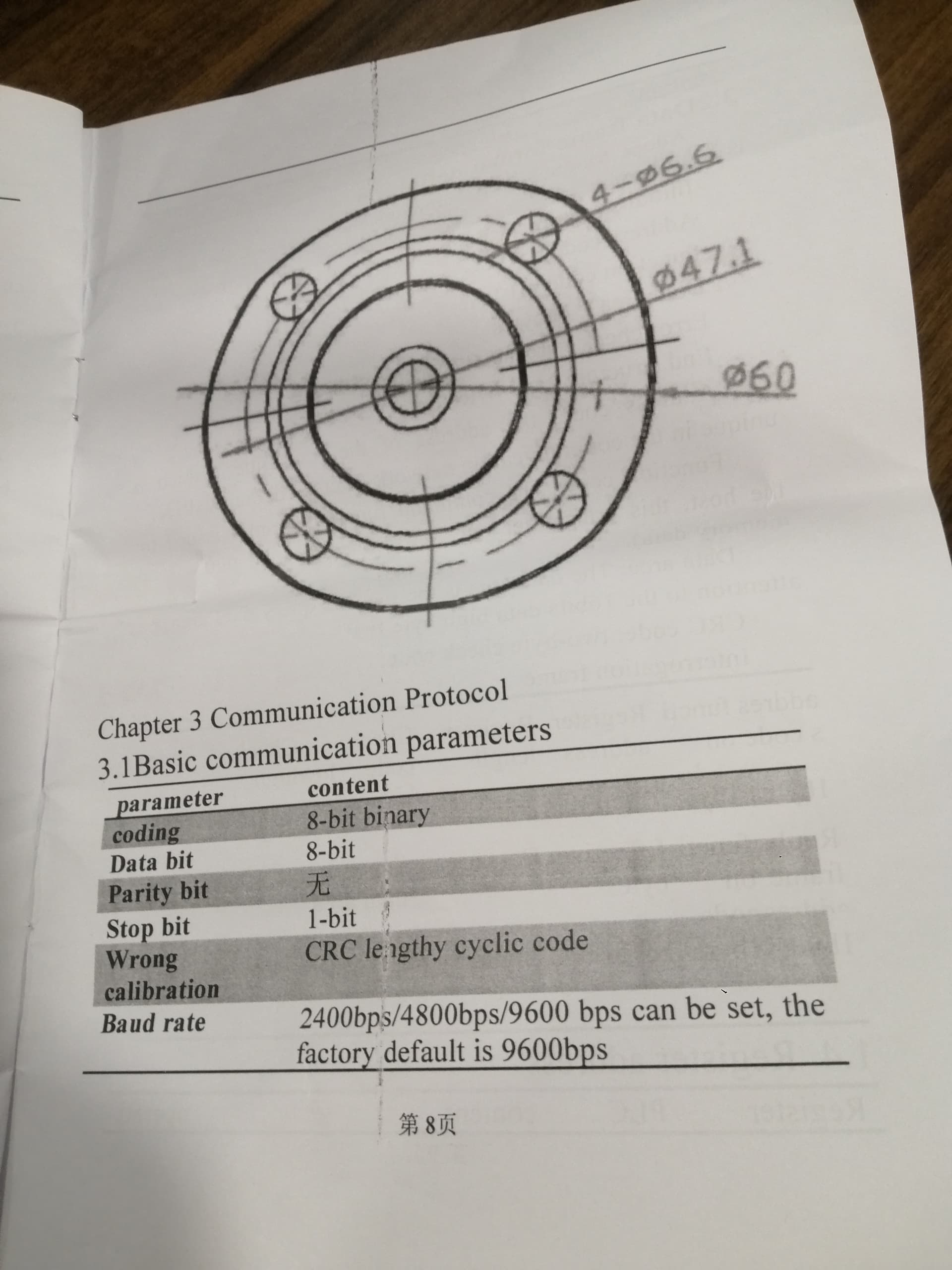
I'm not sure if this will help or hinder you, but I did find another datasheet for your sensor. It was in chinese but google translate had a go at providing an english version: 2010191808_Ubibot-JXBS-3001-FS_C843317 (1).pdf (520.2 KB)
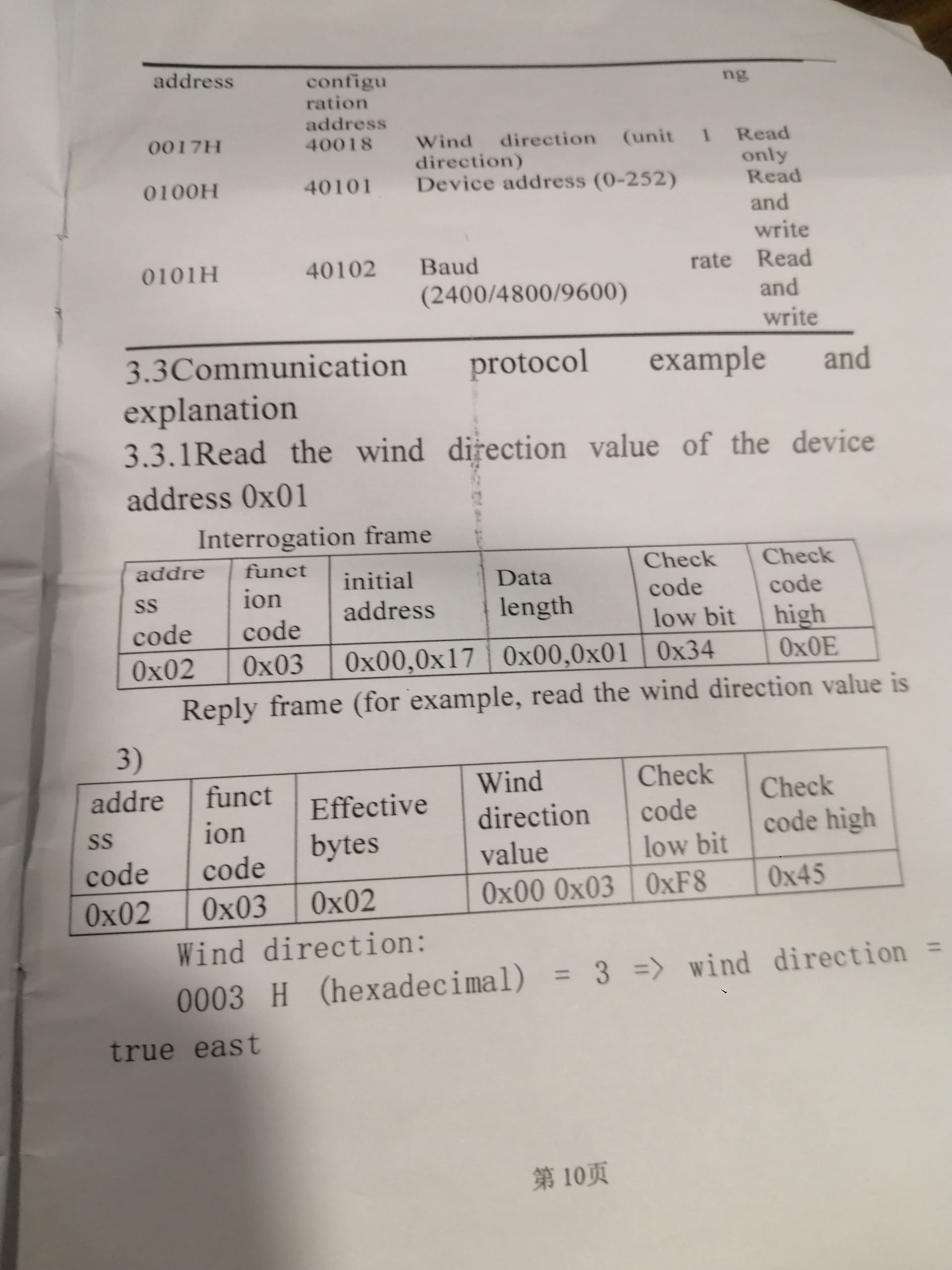
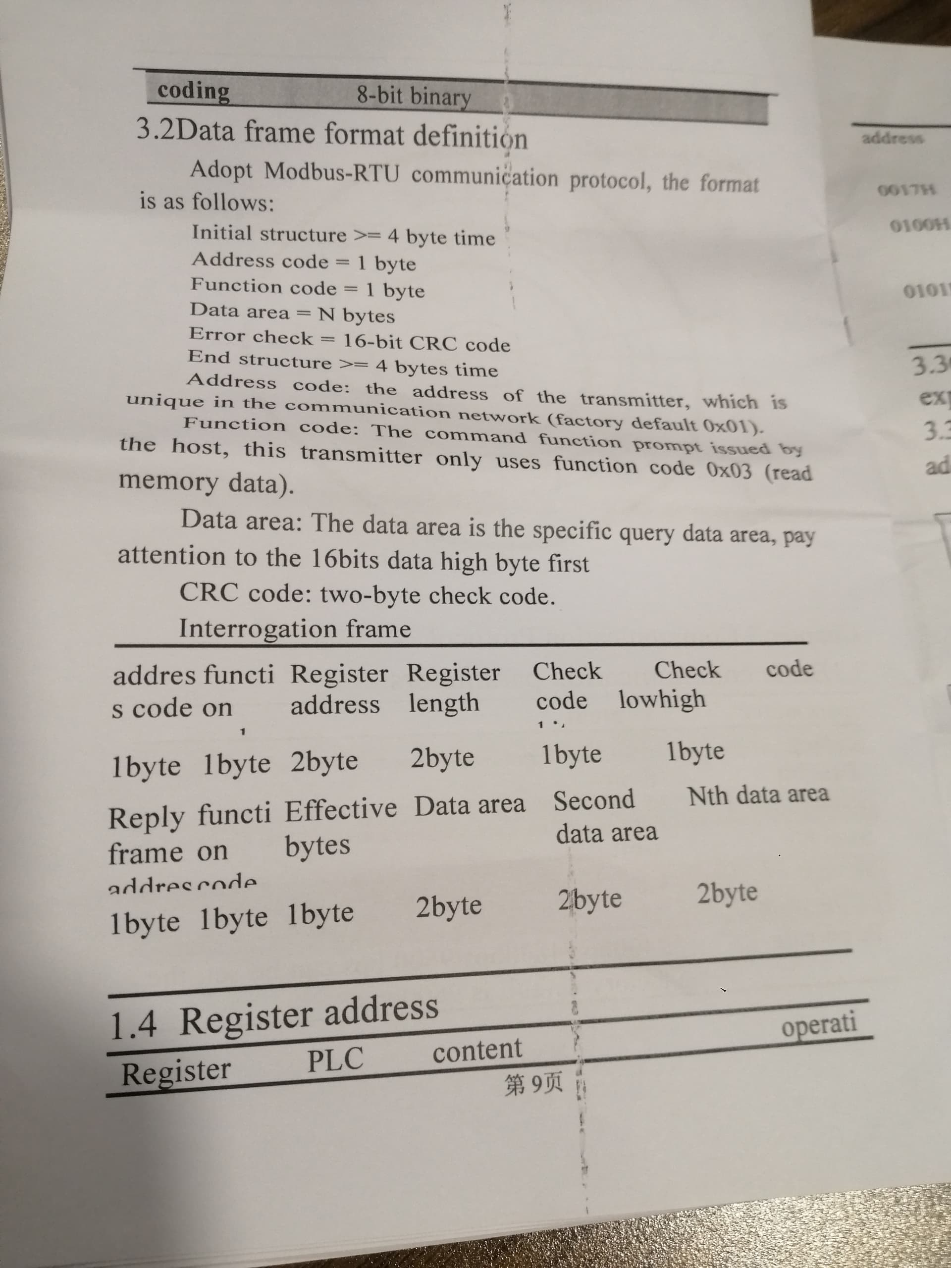
This manual indicates that the device address is 01 and that the wind speed and direction are in the 2 consecutive registers starting at 0x0000.
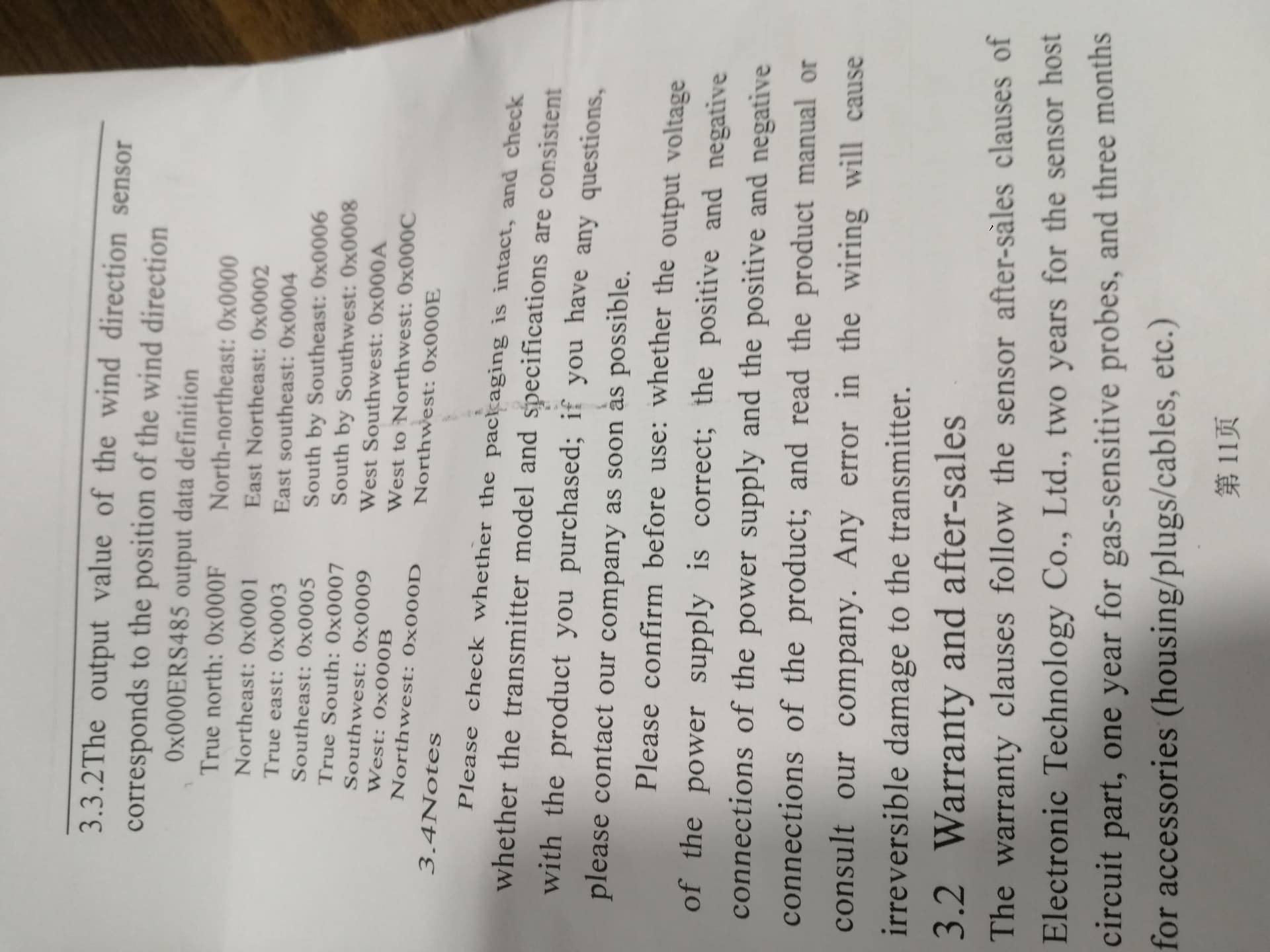
One of the manual pages you copied into the thread says the slave address is 0x01 but in the following example it is 0x02. Try both (bad manual means more work for you).
I would try to read register 256 (0x0100) as it should contain the device address if the returned value matches the address you used for the request you got the right one.