Keithley 168 "repair"

Yes. that is right. I have a Keithley 168 scope


that is in unknown condition.

I had found the old manual here, which is very helpful in my attempts to figure out the connections for the battery header, but got me absolutely nowhere.


Because according to the schematics (manual above), there are 7 1.2V battery connected from pole D to pole C (with pole C supposedly at 8.4V), and two more connected from pole A to pole B (with pole B supposedly at 4.8V)
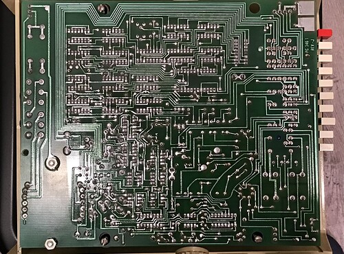
However, the section "how to check batteries" invalidate the previous assumptions because the test pad B is connected to pole C (which is supposedly 0V, connected to the negative lead of the two BA-29 batteries), as shown on the picture of the PCB.

Which means that either figure 8 is wrong, or Table 2-2 and the description is wrong.

Which lead to my attempt to figure out which battery lead is connected to "ground", so I start to probe the battery pins and the "Lo" pin (or GND).
So far, I have found that pin A is connected to GND when the device is NOT in "CHG" mode. Which is supported by the fact that when charging, the battery is connected in series (manual). Which suggest that the two BA-29 battery should be connected from A to B (B being the positive end of the BA-29), rather than the other way around and also validates the fact that the battery probe is on pole B.

So to summarize, this is my current conclusion. Black means confirmed, and blue means unknown.


Let me know if you have any thoughts over the orientation of the batteries (marked in blue).

The voltage requirements require a bit of finesse. I have 9V batteries and Li-ion batteries, as well as AAA batteries and USB input.
My current idea is to use a 2S lithium battery, one across D and C (supplying 4.2V, which is below the recommended 4.8V but way above the "low battery" of 2.5V) and another one across B and A (supplying another 4.2V, which is 8.4V). The two batteries at normal discharge sits at 3.7V, which when in series give 7.2V, still above minimum.
However, I currently have only one .. nevermind. I can "borrow" the one from my Ti calculator. Let me know if you think this idea (of a 2S li-Ion) will work or not.
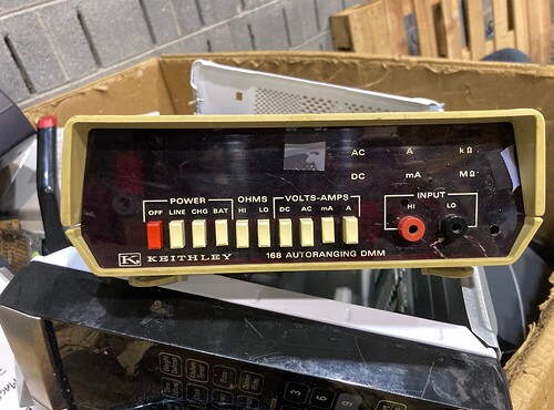
I don't think so. What does the front panel say?

Note: the board is REV J, which is likely a long way from your schematic.

More notes: If the batteries are really listed as 1.2 volts, they are the REALLY old NICAD cells.

1 Like

I think they are 1.2 because they are rechargeable. Modern 1.2V Ni-Mh is also rated at that voltage.
Of course it is old. It's year 1975, if I didn't remember incorrectly.

It says 168.
I don't think the PCB revision is significant as one would expect at least the important bits (e.g. battery pack, AC in, front panel) to at least have the same pins. That said ....


I found it in the schematics. Helpful? Maybe.
However, over here it also mentioned that the batteries are to be 8.4V and 16.8V respectively, which isn't what that is displayed on earlier sections of the manual or the bottom of the case.
There is this regulator-like thing, but the schematic is too blur and raises more questions than answers.

If it won't play, use a good soldering iron and touch up ALL those round pins in the closeup picture of the bottom of the board. The board was wave soldered, but the round pins did NOT have enough flux to allow the solder to flow correctly. They ALL should look like the flat pins inthe upper part of the picture.

Does the manual say if the machine will run under AC power with the batteries disconnected?

1 Like

It does. There are three (four) power mode:
Off, Line (AC power), CHG, and BAT. As mentioned, CHG will only give the system power if the battery is present (since as mentioned in the manual the battery is charging serially).
I'm not going to be dealing with Line or CHG any moment soon.

To be fair, they all look pretty good. The front panel is all smashed up, however. Which don't inhibit usage, but looks sad.

There is a blown fuse on the input, the "mA fuse". Rated at 1/100A 250V, I am pretty surprised they can make a fuse with such a rating. Guess just a bit of really thin solder wire.
If that's the reason this device is thrown away, well, that's a good chance that the device is working when it is thrown away.

But the battery ...

You can fuses at any value if willing to pay!

Ok so last night I tied together my 4.2V Li-ion and a (group of) 2.4V Ni-Mh batteries. I tied the Li-ion from D to C and the Ni-Mh from A to B.
Yes, the voltage is very very low (6.6 combined) but I was expecting at least something to light up.
Nothing happened.

Should I try 9V? I am worried that the 9V might damage the board. Where should I try it?

Yes, I might just "borrow" the neighboring 10A (or actually spend the time to get a mA fuse), before I had the time to hunt down a 1/100 A one.
Please stop posting borderline useless information.

Roger that! Good by

1 Like

Does anyone have datasheet for the UGH7805393 (MCP7805CP)
I know it's a 5V regulator but I want to know the absolute ratings for this thing (and the EXACT model)
Because this device is made over 30 years ago. Yes, we have modern 5V regulators but I'm not swapping out what's not broken.


Looks wrong, except it's not.
Thanks for nothing.

A little wider view of the schematic on page 91 of the manual you linked shows that they are trying to make +5V and -12V for the op amps and biasing:

Batteries with volts above the dropout for the 7805 and the 7812 should work. You need more current on the +5 side, since that's what's running all the logic.

If you put too much volts into the 78xx, the excess is turned to heat, so it is good to be close to the minimum voltage that produces the proper output voltage. 7v and 14V would be normally enough for 5 and 12 V.

The way you'd test what the dropout voltage would be it to put a variable power supply on the input and see what it takes to produce the output. Increasing voltages above that makes increasing heat, up until it burns up. If the regulators don't go above 125C, you're fine.

1 Like

Hm. Interesting. I thought they will merely block the current (acting as a resistor)
But, well, resistors generate heat, I guess?

The problem, however, is that there is no 7V battery. I guess you can use five AA/AAA cells for a total of 7.5V, but boy is that a lot of cells.
We do have 3V cells. I can string two of them together for that. But is 6V enough?

Same situation on the -12V side. We have 12V cells, yes, but again. String together ten AA/AAA cells? or (still) five CR2 cells?
Although it's still better than the original circuit, which used seven on the 5V side and sixteen on the 16.8V side.

Yes, I understand I need more current on the 5V side, but the problem is that 9V cells come in integers and I can't buy 0.8 of one.

I'm probably going to just makeshift the 9Vs I have until they die and lay something out that uses CR2 cells (at least on the 12V side), since 5 cells don't sound like an absolute pain (yet). But I think there will be problems if there are more than one type on the same branch.
I don't think I should use button cells like CR 2032 despite them being quite a good power source.

I don't really mind mixing battery types in builds. My analogue multimeter I bought for the family runs on a 9V and 2 AAA.

You might be able to use a couple LiPOs with adjustable boost regulators, such as what you might find under a search for "3.7V 4.2V 18650 Lithium Li-ion Battery Charger Board Adjustable DC-DC Step Up Module Boost Charge Discharge Integrated Module"

I could. However, boosting and dropping it back down is probably more wasteful than just plonking dry cells in. I should even able to run it directly off a USB if it satisfies the voltage regulator, or replace it with one that have the desired efficiency. At this point picking rechargeable batteries should mostly be environmental concerns

Especially since you must have figured that the scope is able to run on AC.

But I don't want to do any of that -- I'm not replacing what's not broken. In part because I don't need this scope and in part is the intend to preserve it "as is"

There ae multiple power supplies. The big portion runs the device itself. The remaining couple of batteries are the DC current source for the Ohms function. A DC source is needed for noise floor.

I understand. I am merely considering about the potential to use batteries to power the unit.
Which is allowed as there is a optional battery pack for this unit. However as shown in the circuit diagram it is challenging to use anything other than NiCad (that the system is designed with), especially with Li-Ions as they require strict charging regulations and thus I will be charging them separately. However, given the similarities between Ni-Mh and Ni-Cad (electrical characteristics wise) I am wondering if it is possible to use Ni-Mhs as "drop-in substitute" since they also have larger capacity.

It is not too difficult to modify the circuitry so a constant supply will be given (from the main coils) to a lithium-ion charging IC who will be responsible for balance-charge the cells when the "CHG" button is depressed, however as I mentioned I intend on keeping the unit as-original. Unless some component breaks.

Put in a higher voltage battery and a buck or linear converter to get to the voltage you want. Velleman makes a $15 DC-DC module that is adjustable.

1 Like

If you didn't see the previous posts, schematics and pictures, there are on-board regulators (specifically, two) for powering the various components. They are all linear regulators and thus it require more than 5V and 12V to drive them.

In the original Ni-Cad case , 7 cells (8.4V) fed the 5V reg and 16 cells (18.6V) fed the 12V reg. In my previous 9V battery case 9V for the 5V regulator and 18V for the 12V regulator. In my current Li-HV case 2S (8.6V) fed the 5V reg and 4S(15.6V) fed the 12V reg.

(edit: screw Ni-Mh)
There is no way I am going to charge this for 24 hours for 12 hours of usage.

I am just wondering about alternative batteries to power this 2W unit so there is less hassle in recharging them up.

One of which is called "no battieres" where it is ran from AC just like how it was for the past 30 years. Obviously this adds nothing to portability.

This topic was automatically closed 180 days after the last reply. New replies are no longer allowed.