Keyestudio CNC Shield V4.0 Board For Arduino Nano ==--->> Is Anyone Using This ?

Good day to you all,

First off the bat - if you havent got anything nice to say, please, DONT bother replying. Some Parents teach that to their kids, lets hope all who reply to this thread got brought up like that......

Ive been trying to research this Keyestudio v4.0 BLACK PCB that uses an arduino nano clone to operate GRBL to use in CNC machines, for me, im wanting to use this for a really low-power laser engraver, 500mW power for the laser, so its just a trial machine to see if i want to mess around with buying a bigger more powerful and serious laser cutter.

Plus it gives me the chance to play about and learn Arduino, which i can operate, but am pretty useless with coding, but this post thankfully has NOTHING to do with the code. lol

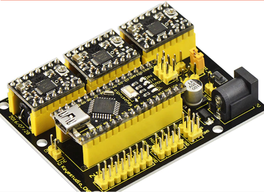
Okay so ive included some pictures from research found online from the official Keyestudio wiki and their link to the Aliexpress buying link which shows how some A4988 Modules are placed in orientation on this Nano-Shield

My Question is, is anyone currently using this shield for a CNC machine (Laser Cutter/Engraaver/Mill/3D Printer etc) and does it work as needed ?

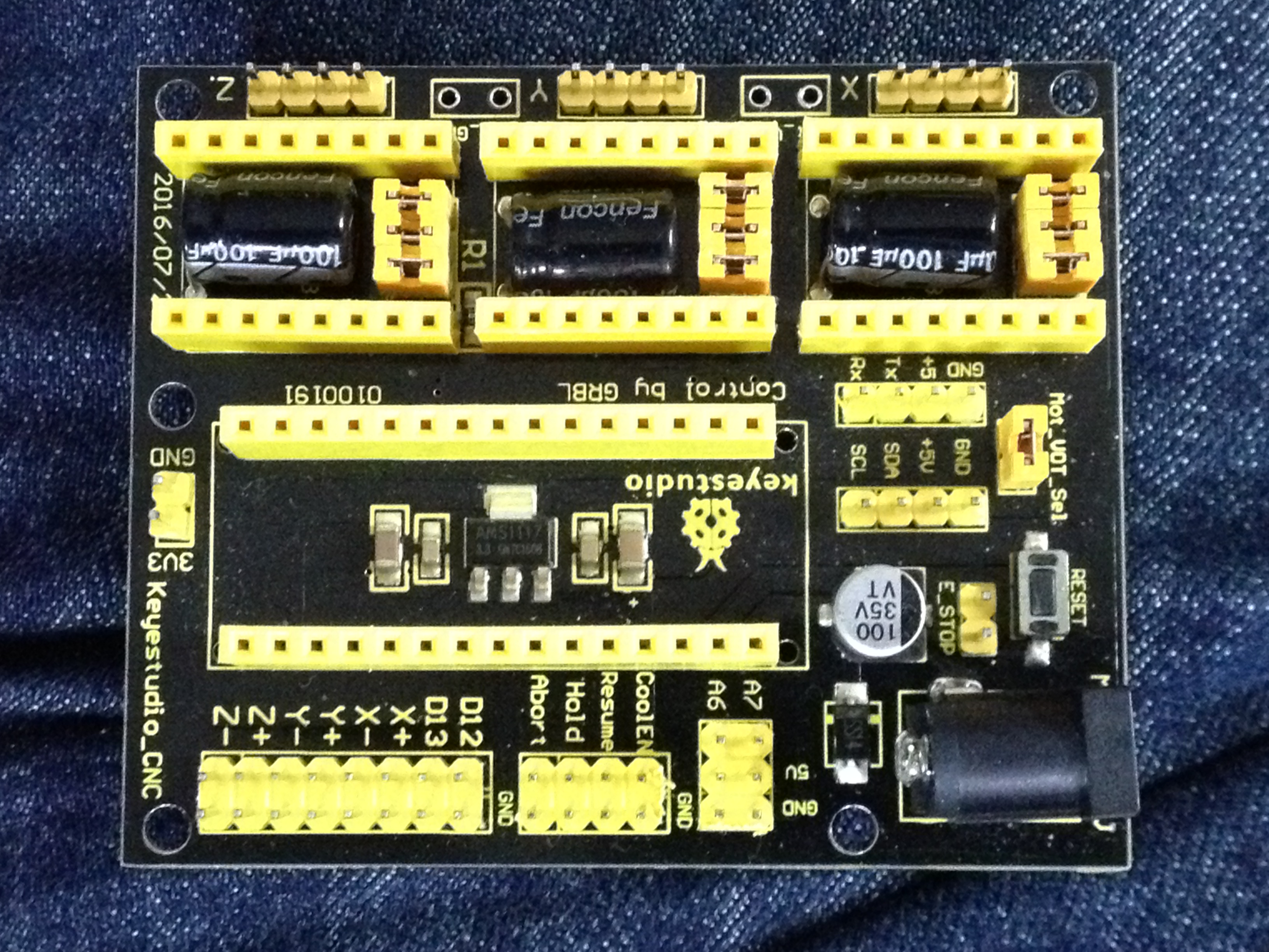
Please kindly note that this is the BLACK PCB, not the RED one, like shown in my pictures.

i also traced the PCB Tracks on the shield from the 'STEP' and 'DIR' pins from all 3 sockets of the A4988 drivers to the Arduino Nano Clone and found that they are connected to the following pins, as it is, with NO Modifications/Alterations to the shield;

Link to Expanded Picture i copy/pasted showing orientation and motor orientation connections on this board

X Motor A4988 Pinout;

Arduino --- A4988
D2 --- STEP
D5 --- DIR

Y Motor A4988 Pinout;

Arduino --- A4988
D3 --- STEP
D6 --- DIR

Z Motor A4988 Pinout;

Arduino --- A4988
D4 --- STEP
D7 --- DIR

Even though there is a way to alter these pins in the code, this i know, but the above is triple-checked painstakingly with a x40 Microscope to see the tracks.

Please could anyone currently using this shield please reply and say how your experience with this BLACK-PCB shield has been and more importantly;

Have you also been able to use the Trinamic TMC2130 Stepper Motor Control Boards in place of the A4988 Driver boards ??

Also hope this post serves others to how to properly connect the stepper control boards (A4988, TMC2130 etc) in the Correct Orientation in the future as a LOT of these boards have been sold around the world

Thanks to all in advance,

please keep this post positive,

those that just cant help posting negativity, please dont bother, move on lol

SOURCES and Thanks to all in these Sources;

Keyestudio Official Wiki

Keyestudio Official PDF

Aliexpress Buying Link

Ebay Buying Link

matelot's Post on Arduino.cc - Previous RED PCB Version of this Shield

how-to on Mechatronics Website (Some pictures copied from here)

Link to Expanded Image, wasnt letting me share this in main post, max attachment limit was reached;

Okay Just waiting for a decent PSU now then i'll be able to power up this baby so in the mean time i can research the pinouts of this PCB as there is NO SILKSCREEN showing where what pin does what on the Stepper Control Boards, a really bad design flaw, i just hope the board works lol

Seeing how theres loads of these being sold via ebay and aliexpress, im surprised no one's replied here lol

Remember, ya negative nannies - stay outta here lol

Here's some photo's of how i think it should be connected;

Photo with Arduino Nano Installed

PS - Sorry but i cant seem to insert photo's all in one reply as this darn system needs me to upload the photo first then to MODIFY the post and then i can select the insert photo button and then save the post then and ONLY then will it work and Actually SHOW my photo in the post but...

As these are high quality photo's they are at the post-limit of 2MB which is per-post limit of photo's so i gotta make a few posts in order to show my progress, wish me luck lol

Remember if anyone is currently running this board, please kindly reply, POSTIVE FOLKS ONLY, thanks loads in advance :slight_smile:

Two Trinamic TMC2130 CLONE boards installed, bought from Aliexpress, so no doubt clones...

Fitted so that the STEP and DIR pins are the same as the A4988 modules were shown in one of my previous photo's, will try to get them to be shown properly here in this post.....

Enlarged photo of Trinamic Drivers for X and Y Axis - Z Axis not needed for Laser Engraver, which is what i will want to be using this for...

Enlarged photo

Close-Up

if you Notice that the Potentiometer is on the LEFT hand side where as the A4988 Stepper modules in my FIRST post's picture shows that the Potentiometer is on the RIGHT hand side but i am going with what the pins say on these TMC2130 boards, mainly the STEP and DIR pins.

Just waiting for a Power Supply now, wont be long :slight_smile:

Also - Has anyone used any I2C Devices when using ANY GRBL Boards, i noticed that there are pins broken out for the I2C bus so was wondering if one could attach a humidity/temperature sensor to that and have it display either on screen or on a 1602 Display ?!?

Hope you're getting on well with your new board. Found this while researching, looks like a nice replacement for my tiny board that came with my laser engraver. Where are the PWM pins for the laser control though?

donde va conectado el laser en ésta placa?

I am in doubt about the power and use of the mot_vot_sel jumper. I will use my USB-connected arduino and intend to power the drivers with a 12V 30A power supply. Should I leave or remove the jumper?