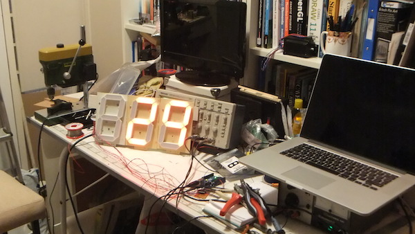
I'm trying to make a clock using a arduino nano, a DS3231 module and 4x1.8inch 7 segment common cathode digits weird as a 4 digits display. I have managed to make it work with a smaller 4 digits display by wiring it directly to the arduino.
I have played around and in order for the digits to properly lit, I need a 12v supply and a 1k resistor.
My problem is that I don't know what kind of component I need to wire between the 12v supply, the digits and the arduinos pins.
What 7-segment displays are you using? (that need 12v?)
I have played with the smaller/normal sized versions of these...
and IMHO.. it cant get much simple than using a MAX7219 chip to control all the leds in your displays..
It multiplexes so fast you think all leds are on at the same time... (the one 'turned on' of course).. but only use very little current. Pretty straightforward chip to use with common libraries out there as well.
Might be worth looking into if it fits your projects needs.
And he is using some mysterious unspecified common cathode digits "weird as a 4 digits display". Very unfortunate as common anode digits are very easily driven with TPIC6B595s per digit.
Maybe if we knew what the digits actually were and how he has wired them, we could offer useful suggestions.
Grumpy_Mike:
You can use a ULN2003A to drive a PNP transistor to make a current source at what ever voltage you want.
Or simply use a PNP and NPN transistor.
From what I read the ULN2003A is a NPN transistor array. Isn't there an array of PNP transistor?
Yes there is, things like the TD62386AP, but you still need something like the ULN2003A to drive the PNP transistor.
This is because the base of the PNP needs to be at the voltage of the emitter to turn it off. As you want to drive it at 12V you need the NPN to get up to 12V before this can be applied to the base.
The TC446x series of quad low-side MOSFET drivers might be useful upto 18V supply - overkill but
you get 4 drivers in one DIL package, although you probably need diodes on the output as them
have totem pole outputs.
Spiridusu:
I have managed to make it work with a smaller 4 digits display by wiring it directly to the arduino.
Please post the wiring diagram between NANO and the smaller 4-digit display unit. Also, post your program codes. It is likely that the power problem for your larger digits could be solved using UNL2003/ULN2803 buffers which are Darlington pair power transistors. The display unit referred to in your Post#8 is a '4-digit Common Anode Multiplexed Type Display Unit.'
Spiridusu:
Does anyone has any idea on what I can do?
Use ULN2803 (50V/500mA) power buffers as per following diagram and change your program logic accordingly. Hopefully, your power problem will be solved with your large 7-segment display devices.
U1 selects a digit (out-of-4); U2 selects a segment (out-of-8). The following demonstration codes ignite segment-A of Digit-1. All other segments of all the digits remain OFF.
Grumpy_Mike:
His display is common cathode so that circuit will not work for him.
Spiridusu:
The digits that I have are the ones in the link and the wiring is the one in the image.
The following is the structure of the 4-digit display unit downloaded from OP's delivered link image. To the best of my knowledge, there are 4 common anode 7-segment display devices whose identical cathode terminals are connected together to make form a multiplexed display unit. Therefore, the circuit of Post#16 should work without a little bit of doubt should the program logic is implemented correctly?
So, which is correct? The eBay auction that says "5PCS NEW 1.8 inch 1 digit Red Led display 7 segment Common cathode" or the schematic clearly showing common anode? Both were posted by the OP in the same sentence.

