Hi guys, this is my second post here. I need some help to multiplex these 4-inch seven segment display to create a gps clock using arudino uno
From the knowledge I gathered, to display the time on the large seven segments i need driver and a switching circuit to display the relevant time. After testing i found it needs 9V 40ma to drive it.
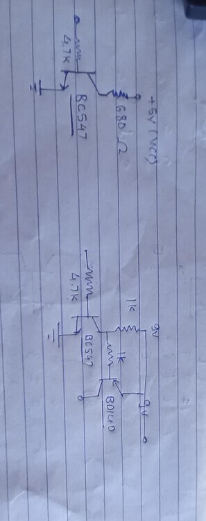
This is the circuit i am reffering . Now i am getting a bit confused on how to multiplex the display through transistors like bd140 and bc547 and the deadline is tommorow.
I assume you have those large displays because you want to see them from far away, and maybe in bright light. If so, then forget about matrixing. If you matrix four digits, then each digit is lit up 1/4 of the time, which is roughly half the percieved brightnes a digit could be.
If you want performance, then use four TPIC6B595 chips (or a member of that TPIC family).
Leo..
@Wawa Hi Wawa, thanks for your input, I plan on multiplexing those dispalys with the help of 74hc595 shift register which is different from what u mentioned but guess it will get the work done.
I have two options, one is shift register and other is creating a driver and switching circuit using transistors like this
Yep, same difference.
74HC595 - TPIC6B595
Spot the similarity?
A TPIC6B595 is a HC595 on steroids.
It has high voltage/ high current outputs, so you don't need an ULN.
Just one chip per digit, one 100n ceramic decoupling cap on it's 5volt supply, and seven current limiting resistors for the seven segments. Nothing else (apart from the Arduino).
Leo..
Again, you say you want/plan to multiplex the displays. I asked why before but you did not answer.
With multi-digit displays, you have no choice except to multiplex because both the digit and the segment pins are commoned.
But with your individual displays, you have the option not to multiplex. This will make your display brighter and flicker-free and your code much simpler. It may take a few more components.
I still cannot see your Tinkercad diagram, please post an image of it here on the forum.
For your hand-drawn schematic of the anode and cathode drivers, the anode driver looks ok but the cathode driver makes no sense, I guess that is an error. Where does the display cathode connect to the circuit, and why is the npn collector connected by a resistor to 5V?
Both, because a digit is seven segments.
A TPIC chip has 7 outputs, so one spare output for a decimal dot (if needed).
Two flashing dots between hours and minutes could be added with that.
Note that TPIC chips can only drive common anode displays.
Leo..