Large display web counter

Hi everyone!
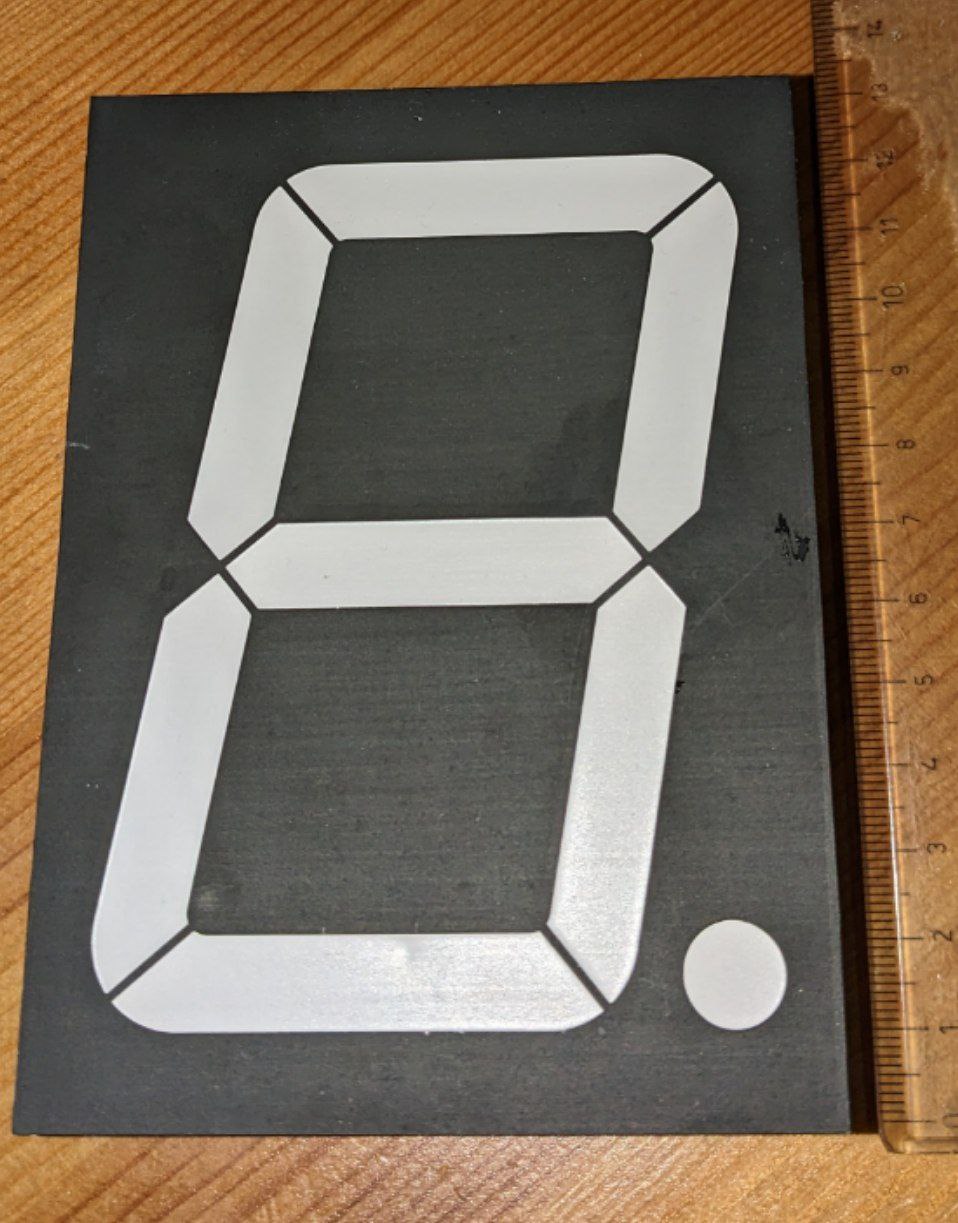
I bought some very large 7 segment displays, with following current specifications:

  • Forward Current Per Segment: 30mA
  • Peak Forward Current Per Segment (Duty 1/10, 1KHZ): 150mA

I would like to connect 5 of them to an Arduino board, to display numbers from 00000 to 99999. I don't have an Arduino for that yet.

My question is: How do you suggest I connect it? Using a specific driver? Do I find anything that already supports that current?
I also have to choose my arduino, and I will need it to connect to the internet to curl a web page where I store the number to be shown on the display. So every suggestion about what board I should buy is very welcome, considering it will also have to connect to a wifi board (or have native wifi).

Thank you very much for your help!

Nicola

What is a dimensions of your displays?
I think it would be easier to use LED matrices

ESP8266/ESP32 as WiFi + controller. For the display's 1IC MAX7219.
How many volt/segment? Datasheet?

Hi @nicolafiorello,

there is a youtube video showing how to use ULN2003 as drivers for 7 segment displays:

https://www.youtube.com/watch?v=SVnkn7Q40bs

I suggest to use a ESP32 board as controller; it's easy to program with the Arduino IDE, provides Wifi and a lot of RAM and is not very expensive. And you will find a lot of examples/projects that may already deal with your requirements ... like e.g. Use of Lib CURL with ESP32

Good luck!
ec2021

5 x 7 segment need 35 IO. ESP don't have that. Then you must going multiplexing.
5 IO display control + 7 IO A-G segment = 12 IO.
7 x 30mA = 210mA/display. That is to much for the controller. The ULN2003 (7 IO) or ULN2008 (8 IO) as (sinking) driver for CA display's is OK but then you need a source driver like MIC2981 too.

Contra, you must do the multiplexing in software. A little hookup in the code you can see the brightness difference.

The MAX7219 do the multiplexing for the user. Every digit is even bright. Only 3 IO to use.

I guess you haven't watched the video :wink:

This is how they explain it there (with an Uno!):

4 displays are addressed by 7 pins (to control segments) and 4 pins for the multiplexing = 11 pins in total. So a fifth display would require 12 pins.

You would of course need 5 ULN2003. The diagram from the Texas Instrument datasheet shows

image

that each output may drive around 160 mA if all seven channels are run with 100% duty cycle.
(Source: https://www.ti.com/product/ULN2003A )

I agree that the MAX7219 is easier to use (have some in my stock :wink: ).

As the TO has already bought some displays, it might be a solution to use the ULN2003 ...

But I also fully agree with you that multiplexing has an issue with brightness! Your code has to be non-blocking and that makes things sometimes more difficult. With an ESP32 it might be interesting to use FreeRTOS ... ?!?

ec2021

It still way complicate than led matrices :slight_smile:
LED panels not needs any additional chips, has very easy connections and can be very large (up to few meters high) for quite moderate prices.

I agree...

But sometimes the easy way is not as satisfying (after frustrating) as the more complicated solution... :wink:

Actually some exercise tasks for technical students are based around multiplexing seven segment displays ... just to keep it not to easy...

ec2021

1 Like

What IC is there on the led panels to drive them? Indeed the MAX7219.

One MAX7219 can drive 8 7-segment displays. TS has the displays. I think he will use them.

But that isn't the first way as the TS don't know how to multiplex the display's. That is more sophisticated use of the ESP32.

The current for the ULN isn't the problem. But the display's need source too. Worst case @30mA * 7 = 210mA. What say the ESP32 datasheet?


Ioh VDD_SDIO 20mA and as note 3
. 210mA is more then 10 times the specs. That is why I say to use a highside driver like MIC2981 similar to the UDN2981 or TD62783AP.

Of course not.
One LED matrix contains at least 512 pixels. How much would it take 7219 for it? There are more smart drivers have been known for a long time.

But the main thing is that they are already built into the matrix, you don’t need to solder or wire anything

Ok, good luck.

I did not recommend to drive the displays from the ESP32 pins ... :wink:

Think we are talking the same things: Actually, the ULN2003 is a device to control external higher voltages and current by controllers!

See here for an example:

https://www.makerguides.com/28byj-48-stepper-motor-arduino-tutorial/

The technical parameters of the ULN2003:

image
(Source: https://www.ti.com/product/ULN2003A)

You can control up to 50 VDC external power at up to 500 mA by CMOS/TTL compatible 5V input as it is a darlington transistor array with 7 channels.

Of course you need an external power supply (as with the other drivers as well).

Due to the fact that each channel includes also a protection diode they can be used with relays without an external protection diode.

ec2021

Hi everyone!
Thank you for all your answers, I see a lot of interesting information.

On my display order there is this code: BS-AE04RD so I think that's the product's datasheet datasheet BS-AE04RD

I took a picture of one display element

I would like to use 5 of this elements, that I already have, instead of other types of displays. I also add a detail I forgot: I will need a free digital out pin for another use, so I should consider that wen I choose the board.

Again, thank you very much for your help!

The voltage needed to drive this display is too high for most above solutions.
The common way to drive these is with a shift register chip from the TPIC family.
Read this.

Beware of using an ESP.
These are 5-volt logic only chips.
Leo..

1 Like

Yes. I have one of these displays and I use TPIC595 to drive it. Only requires 3 pins for as many digits as needed.

@cedarlakeinstruments do you have a schematic with common anode display and a sketch available?

It's all in the link in post#14.
Schematic, code etc.
Try the documents tab on that page.
Leo..

Yes, all my wiring & code when I did this was from the Sparkfun examples.

This topic was automatically closed 180 days after the last reply. New replies are no longer allowed.