Hello, I am looking to plan out a design for a very large analog wall clock powered by a specialized stepper motor and controlled by an Arduino board with accessories. I've done a small amount of research and brainstorming and have narrowed down to some key components while I'm working out the remaining details.
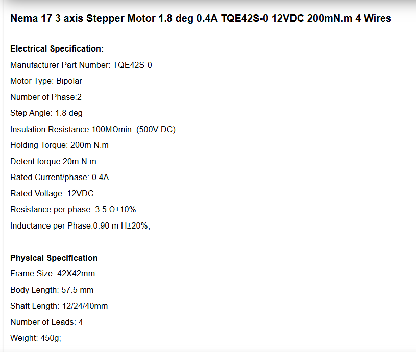
One key component is the stepper motor; Since I'm wanting second, minute, and hour clock hands, I either need a special motor or some complex design with multiple motors. Fortunately I have found a TQE42S-0 NEMA 17 stepper motor which has 3 nested drive shafts and I believe with the right wiring would be excellent for this project.
For the Arduino board, I was looking at the ESP32 for its WiFi capability which I could use to sync time against NTP.
Additionally I wanted to wire up a DS3231RTC to keep accurate time and then use the NTP sync for any adjustments.
The clock hands themselves I would need to do further research and experimentation on due to the size of the clock. I'm leaning towards some type of long thin aluminum design, but I'm not that far along with this component yet.
I have an existing large metal(non-ferrous) wall clock(50 inches?) that uses a very simple battery clock that I am going to swap out for this project.
I'm pretty confident in the fundamentals of this design in terms of getting and correcting the time digitally, and having the code to control the stepper motor. Where I have concern is any corrections that need to be done through the motor itself. I'm trying to think of a feasible homing and zero-position solution to keep the clock arms in sync. In my research I've identified a few different approaches including optical sensors, hal effect sensors with magnets on the arms, and induction sensors that detect the aluminum arms. I've found challenges with each solution and I haven't been able to narrow down to any of these or an appropriate alternate solution. A big concern I have is the limited detection distance of these approaches in contrast to the clock hand that will have to be furthest away from the sensor. Additionally, there's a challenge where some detection methods will be triggered for the hour hand position by the second and the minute hands though I believe this could be compensated for with some code logic. This part honestly is where I'm seeking the most guidance.
I am happy to provide any links to components where requested, and any guidance would be appreciated. Thank you.
That is an interesting stepper, and a reasonable choice for your clock.
The simplest method of homing a stepper is to send enough pulses to run the shaft into an end stop, which will not damage the motor.
For a clock, you could use a solenoid to extend a pin out of the clock face, at for example the 12:00 position, to act as the end stop for all three hands. Retract the pin after the homing operation.
Thank you for the suggestion. I was hoping whatever method I use for homing to also be used for correcting the movement of the hands against drift over time. I was thinking if I use a contactless method, that would be a good route to take to gauge if movement drift has happened and to correct it, but I still have concerns about the minimum distance any sensor might need and how far spaced the clock hands will be from each other.
Alternatively, going with the pin on a solenoid solution for the homing operation, I figure I could just periodically "reset" the hands back to zero with the homing pin out, and then just repeat that every so often as needed since I believe this set up will be fairly accurate on its own over a decent period of time.
I like the contactless approach better in theory since I could correct so frequently that I'd essentially never need to worry about drift on the hand movements, but I'm open to any particular solution that might work.
Thank you, and I did have some concerns on that. I was hoping with the DRV8825 stepper motor driver that I'd be able to do microstepping, but being honest this is my first time messing with stepper motors and stepper motor drivers so this is just based on the research I've tried to do.
Ultimately if I was restricted only to full movements, the clock would have somewhat erratic hand movements that would be a rough approximation of what the step should be, but honestly I would rather use this type of motor than have to deal with three physically separate motors and gears(or similar mechanism) as I don't feel as capable going that route. I'd probably deal with having the erratic hand movements than try to make three separate motors work, though I don't mind going outside of my comfort zone for a solution that yields a much better outcome.
Your code may have to add or subtract a step from time to time, in order to keep up with international timekeeping, but with a properly designed system, re-homing of the hands should be needed only after power failure.
Forget gears. Use pulleys and cog belts. Size the pulleys to get the movement you want and you can easily use three different stepper motors. Your clock seems to have lots of room to play with.
Thank you. I like being able to use belts, but my main concern here is that for the hand movements I would need to have the drive shafts they are connected to be nested one inside the other, and I am concerned about being able to fabricate that sort of component.
Thank you, this is good to know. I had confidence in the relative accuracy of normal analog clock movements, but I wasn't sure how challenging it would be with a generic stepper motor but it sounds like I was overthinking it.
Yes, concentric shafts with each having it’s own pulley and supporting bearings. Start now learning how to build things, I did and you certainly can, as well.
Dig around on your search engine and you'll find blogs etc of some amazing analogue clocks.
Many use the MSF or DCF77 "atomic" clock transmission. The MSF signal is based on the UK National Physical Laboratory (NPL) output and is transmitted on 60-kHz as a code.
Modules are available which can decode this and also provide a very accurate 1-second pulse. GPS is an alternative.
Personally, I like time to be correct. A central time master clock sending data to slave clocks, like the old office Gents system. I had XBees transmitting the code.
A stepper with gearbox and just some brass tubes and rods can be a thing of beauty and I saw one example of an Ikea glass faced lantern housing the mechanism, like a carriage clock. Other types use the railway station flipper displays.
Probably not necessary. The ESP32 core's software RTC syncs every hour by default, and shouldn't drift significantly over that period. So you can simplify your design.