Setting the time in a wall clock

Hello.

I'm currently trying to develop a mechanism to change the time in an analogic wall clock. Most likely, one of these.

The goal is to be able to enter a time (hour and minute) into the Arduino and quickly have the clock showing that time.

I've considered approaching it the same way Cibo Mahto did but as all the clocks I've seen take steps in seconds (even the ones that don't have the seconds hand) they probably wouldn't be able to change the time that fast.

Also, the clock won't really need to function properly, it just needs to show the input time.

So, I think the easiest way to do this is to connect a stepper motor to the time setting knob these clocks usually have.

I'm using an EM-257 stepper driven by a Duemilanove, much like in this video, which is working perfectly.

The part I have no clue how to do is how to mechanically link the stepper motor to the wall clock. Googling about it has proven to be somewhat fruitless.

I'd very much appreciate it if someone could provide me with some insight on how to solve this problem or point me in the right direction.

Sometimes a piece of flexible plastic tubing, like aquarium tubing, makes a good ad-hoc shaft coupler. It might help to build up the setting knob with vinyl tape or something similar.

-br

Another possibility is to start with a radio-controlled clock movement. These are designed so that you can step the minute hand (and hence the hour hand) independently of the second hand.

Except mechanical side of things (where back side picture would be more useful), I was thinking that arduino would also need to read a current position of hands, at at least at one point for self-calibration. To read, two IR proximity sensors installed on front panel or just behind with two small hole may do a trick.
Is it would be the same clock, or this for multiple - production?

Radio-controlled clock movements must include some sort of sensor, but I don't know the details. My guess is that they know when they are at 12:00 and rely on counting steps from there.

btw another way of solving the problem would be to buy a cheap radio-controlled clock and use the Arduino to generate a substitute radio signal, using a coil of wire to couple it to the clock's antenna. The radio frequency used is low (e.g. 60kHz in the UK), so it can be generated by one of the timers in the Arduino.

Thank you all for your replies.

billroy:
Sometimes a piece of flexible plastic tubing, like aquarium tubing, makes a good ad-hoc shaft coupler. It might help to build up the setting knob with vinyl tape or something similar.

-br

That's an interesting approach which would certainly simplify things, though I'm not sure on how sturdy of a connection I'd be able to make.

Magician:
Except mechanical side of things (where back side picture would be more useful), I was thinking that arduino would also need to read a current position of hands, at at least at one point for self-calibration. To read, two IR proximity sensors installed on front panel or just behind with two small hole may do a trick.
Is it would be the same clock, or this for multiple - production?

I've considered that, though in an early stage, in order to keep it simple, I'd most likely just have the user input the initial time the clock is showing and have the software work around that.

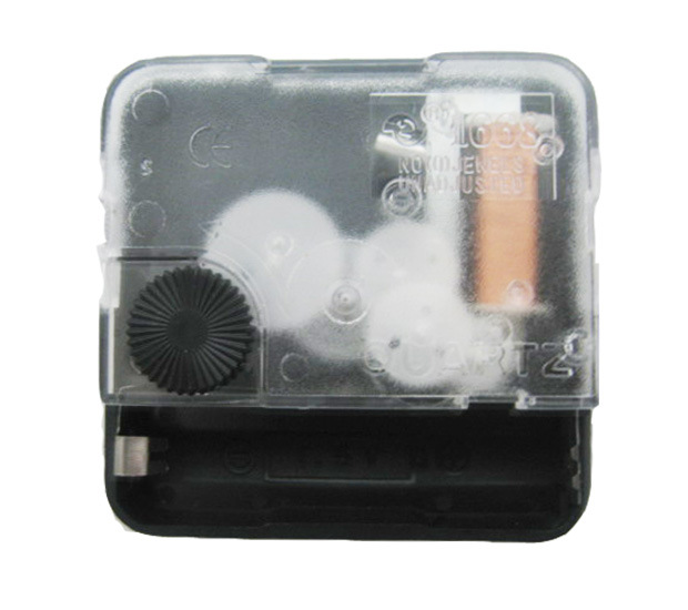
I'm sorry I'm unable to provide any backside pictures, as I don't actually own one of these yet. I'll probably try to swing by Ikea one of these days. Anyhow, they're probably similar to this.

I'm trying to get a working prototype by now, but I do intend to produce a small number of these.

dc42:
Radio-controlled clock movements must include some sort of sensor, but I don't know the details. My guess is that they know when they are at 12:00 and rely on counting steps from there.

btw another way of solving the problem would be to buy a cheap radio-controlled clock and use the Arduino to generate a substitute radio signal, using a coil of wire to couple it to the clock's antenna. The radio frequency used is low (e.g. 60kHz in the UK), so it can be generated by one of the timers in the Arduino.

That's a brilliant suggestion. I had no idea of how widespread these RC clocks were or that they took steps in minutes.

I like both of your approaches. I think using the Arduino to generate a radio signal would be an elegant solution, although from the videos I've seen on youtube they don't seem to move as fast as I'd like. Also, how would I guarantee the 'main' radio signal wouldn't override the generated signal?

I think I might get a faster movement if I made the minute hand take quicker steps, as you first suggested, though I have no idea on how fast I could push these.

Strapa:
I think using the Arduino to generate a radio signal would be an elegant solution, although from the videos I've seen on youtube they don't seem to move as fast as I'd like. Also, how would I guarantee the 'main' radio signal wouldn't override the generated signal?

The one I have takes 14 seconds to advance by 1 hour, and always moves the hands forwards. So the worst-case time to move the clock to where you want it would be about 3 minutes. However, from power up, my clock moves the hands to 12:00 and waits for about 2 minutes before moving the hands to the right time. So it may also take 2 minutes to respond to a change in the radio signal.

The radio signal is quite weak, so you wouldn't have any trouble overpowering it with a signal from the Arduino - until you turn the Arduino off.

If you took a radio controlled clock movement apart and drove the steppers directly, I think you could advance it much faster. The movement of the hands is jerky when my clock is setting the correct time, suggesting it it capable of more speed, and you could run the stepper from a higher voltage.

I think the safest bet might be to drive the stepper directly as you suggested.

I'm going to order one of these off of Amazon and explore it further
Thank you for that! :slight_smile:

Meanwhile, I'm still open to any suggestions on how to solve this using the EM-257. :grin:

Strapa:
Meanwhile, I'm still open to any suggestions on how to solve this using the EM-257. :grin:

Do you have any packaging constraints? If not, simply mounting the stepper motor so that the output shaft was in line with that adjuster would be the easiest approach. Once it is in position, connecting the two parts would be easy to do using epoxy, a small piece of shaft similar diameter to the stepper motor output, and a piece of rubber hose which was a push fit over both parts.