Thank you for your interest in this development and positive comments.
The main use case will be interfacing to an application which uses one of these LCD 1602 or similar displays, but where the source code is not available. It could be, for example, a volt meter and the user wishes to change the display to another type. It is actually more of a tool box or framework than a ready made solution.
The latest version is V0_06 and that is attached to post #11. There are some unique edge cases which that version does not cover, for example reverting from 4 bit mode to 8 bit mode.
If you have such a concrete application and you need help with the program, just add the details to this thread and I'll see if I can help.
Hello, I have tested the program "LCD1602_sniffer_V0_06.zip" with the arduino nano and it has worked well. I made a small modification so that it does not detect the 8-bit bus. Here are the tests. Thank you
//Sniffer LCD
#include "Fifo.h"

Fifo queue(50);
volatile uint16_t errorCount = 0;  // indicates Queue overflows if the queue is not cleared fast enough in the loop()

char sBuff[50];  // for sprintf

enum class State : uint8_t {
  startUp,
  getInitSequence,
  mode4bit,
  mode8bit
};

State state = State::startUp;
State oldState;
uint32_t stateEnteredAtMs;

// expandedBuf byte 0 is control information ( RS [bit1] and RW [bit0] from the LCD and an error flag [bit7]
// expandedBuf byte 1 This is LCD D7 to D0. In 4 bit mode, it is concatenated out of two 4bit nibbles.
uint16_t expandedBuf = 0;


void setState(State newState) {
  // handles state transitions
  Serial.print(F(">>Setting state to = "));
  Serial.println((int)newState);
  oldState = state;
  state = newState;
  stateEnteredAtMs = millis();
}


void readLcdBus() {
  // ports D and B are put on queue when LCD enable is falling.
  // called from external interrupt
  uint16_t buf = PIND;
  buf <<= 8;
  buf |= PINB;
  if (!queue.isfull()) queue.push(buf);
  else {
    errorCount++;  // queue overflow
  }
}


bool analyse(uint16_t portDB) {

  bool expandedBufIsValid = false;  // function return value
  static uint8_t count = 0;         // used in 4 bit mode to determine if we are reading the high or low bits.

  static bool errorFound = false;

  static uint8_t consecutiveInitSequenceCount = 0;

  // connection
  //                                                                8 bit mode only
  // Lcd          -   -    E   RS   RW    D7   D6   D5      D4     D3   D2   D1   D0  -    -    -
  // Arduino pin  0   1    2    3    4    5    6    7       8      9    10   11   12  13   -    -
  // Port         D0  D1   D2   D3   D4   D5   D6   D7      B0     B1   B2   B3   B4  B5   B6  B7


  // bulk read of ports (copy from function input parameter)
  uint8_t pinD = (portDB >> 8) & 0xFF;
  uint8_t pinB = (portDB)&0xFF;

  bool functionSet8bit = (pinD & 0b10000000) && !(pinD & 0b01111000) && (pinB & 0b00000001);
  bool functionSet4bit = (pinD & 0b10000000) && !(pinD & 0b01111000) && !(pinB & 0b00000001);

  // process 4 bit data

  if (count % 2 == 0) {
    // first pass
    expandedBuf = 0;

    bitWrite(expandedBuf, 9, bitRead(pinD, 3));  // RS
    bitWrite(expandedBuf, 8, bitRead(pinD, 4));  // RW
    bitWrite(expandedBuf, 7, bitRead(pinD, 5));  // D7
    bitWrite(expandedBuf, 6, bitRead(pinD, 6));  // D6
    bitWrite(expandedBuf, 5, bitRead(pinD, 7));  // D5
    bitWrite(expandedBuf, 4, bitRead(pinB, 0));  // D4
  } else {
    // second pass
    bitWrite(expandedBuf, 15, errorFound);
    bitWrite(expandedBuf, 3, bitRead(pinD, 5));  // D7 (D3)
    bitWrite(expandedBuf, 2, bitRead(pinD, 6));  // D6 (D2)
    bitWrite(expandedBuf, 1, bitRead(pinD, 7));  // D5 (D1)
    bitWrite(expandedBuf, 0, bitRead(pinB, 0));  // D4 (D0)

    // second pass complete so release the data
    expandedBufIsValid = true;
  }
  count++;
  return expandedBufIsValid;
}


void setup() {
  Serial.begin(115200);
  Serial.println("starting sniffer ...");

 // setState(State::getInitSequence);

  // LCD  "E" (arduino pin 2) is the Enable and we use the falling edge
  attachInterrupt(digitalPinToInterrupt(2), readLcdBus, FALLING);
}


void loop() {
  static uint32_t lastLoopAtMs = 0;

  if (millis() - lastLoopAtMs > 3000) {
    // print out errors occasionally
    //Serial.print("errorCount= ");
    //Serial.println(errorCount);
    //Serial.println(F("Still waiting for data LCD . . . "));
    lastLoopAtMs = millis();
  }

  if (!queue.isempty_locked()) {
    if (analyse(queue.pop_locked())) {
      // here if expandedBuf is ready to be read

      static char charBuffer[80] = { ' ' };  // for presenting a stream of characters obtained from the LCD data bus.
      static uint8_t charBufferIndex = 0;
      bool isChar = ((0b00000011 & (expandedBuf >> 8)) == 0b10);  // RS == 1 and R/W = 0 (crude test for a character)

      if (isChar) {
        char prCh;
        uint8_t expBuf = expandedBuf & 0xFF;
        (expBuf >= 0x20 && expBuf < 0x7F) ? prCh = expBuf : prCh = '.';
        snprintf(sBuff, 50, "control  data 0x%02X  0x%02X  \'%c\'", (expandedBuf >> 8) & 0xFF, expandedBuf & 0xFF, prCh);
        if (charBufferIndex + 1 < sizeof(charBuffer)) {
          charBuffer[charBufferIndex++] = prCh;  // just the data part
          charBuffer[charBufferIndex] = 0;       // clean ahead
        }
      } else {
        snprintf(sBuff, 50, "control  data 0x%02X  0x%02X ", (expandedBuf >> 8) & 0xFF, expandedBuf & 0xFF);
        if (charBufferIndex > 0) {
          // dump charBuffer
          Serial.print(">>>>>>>>>");
          Serial.println(charBuffer);
          Serial.println();
          charBufferIndex = 0;
        }
      }
      //Serial.println(sBuff);
    }
  }
}  // loop()
// LCD test

// include the library code:
#include <LiquidCrystal.h>

// initialize the library by associating any needed LCD interface pin
// with the arduino pin number it is connected to
const int rs = 12, en = 11, d4 = 4, d5 = 5, d6 = 6, d7 = 7;
LiquidCrystal lcd(rs, en, d4, d5, d6, d7);

void setup() {
  // set up the LCD's number of columns and rows:
  lcd.begin(16, 2);
  // Print a message to the LCD.
  lcd.print("hello, world!");
}

void loop() {
  // set the cursor to column 0, line 1
  // (note: line 1 is the second row, since counting begins with 0):
  lcd.setCursor(0, 1);
  // print the number of seconds since reset:
  lcd.print(millis() / 2000);
  delay(2000);

  lcd.clear();  lcd.setCursor(0, 0);
  lcd.print("JAIME ACOSTA");
  delay(2000);
    lcd.clear();  lcd.setCursor(0, 0);
  lcd.print("hello, world!");
}


It looks like you have had success with it. Thanks for reporting back. Have you an application for it or was this simply a test ?
Incidentally, I found a request for such a tool in an old Arduino Stack Exchange thread. Someone wanted to interface to a programmable logic controller which used such a screen. I've now added to the thread there.
I'll say this again.
The sniffer is incorrectly handling the initialization sequence and transition to 4 bit mode. The interface is actually much less complex.
There is no initialization state for the hd44780 communication protocol.
The hd44780 interface is actually quite simple / dumb.
Many people assume there is some kind of state related to the 4bit vs 8 bit initialization function sequence but it is not the case.
There is just a 4 pin mode and and 8 pin mode on the physical interface; that is it.
The high level communication interface for instructions is stateless and is always 8 bits.
The internal micro controller always interprets instructions as 8 bits internally.
The only difference between 8 bit and 4 bit mode is that in 4 bit mode the h/w front end builds the 8 bit instruction from 2 nibbles presented on DB4-DB7 vs reading all 8 bits at once on DB0 to DB7.
Each instruction is interpreted as it comes in with no regard to whether the host or the LCD are in nibble sync;
The LCD micro controller on the LCD does not have to worry about or even consider any past/previous state or whether the h/w interface is in 4 bit or 8 bit mode or whether it is in nibble sync with the host.
The LCD just processes 8 bit instructions that are pre-built by the h/w front end.
Yes it is possible that things are out of nibble sync between the host and the LCD, and when that is the case, the instructions are misinterpreted by the LCD. That is ok, and is accounted for by the initialization sequence.
The Initialization sequence is how the host and the LCD get back in sync.
But again there is no state for the initialization sequence used to get back into nibble sync, that isn't how the instruction communication works.
The initialization sequence instructions along with the bit patterns in the actual FUNCTION SET instruction were very carefully chosen such that when the initialization sequence completes the host and the LCD will be back in sync and the during the process the micro-controller on the LCD is not tracking any state at all.
The sequence allows the LCD micro controller to simply process each instruction as it comes in with no regard to any previous or past state or concern for nibble state with respect to the host.
And yes there can be "garbage" instructions processed during the sequence, but that is accounted for by the sequence not by any state.
I have a big write up about this in the hd44780 library in the hd44780.cpp module.
There is one key thing on the LCD h/w.
When using 4 pin mode, the unconnected pins (DB0 - DB3) will internally be pulled low. This is critical since when the LCD is in 8 pin mode, like at power up, it will look at DB0 to DB7 and the initialization sequence depends on DB0 to DB3 pins being read as zero when not connected, to ensure that the sequence will complete with the host and the LCD in nibble sync with each other.
IMO,
a sniffer should work like the LCD and interpret the interface the same was as the LCD.
The ISR collect() function can be very dumb, it only has to know about 8 bit vs 4 bit mode.
In 8 bit mode it reads DB0 to DB7
In 4 bit mode it reads DB4-DB7 and composes bytes every other call.
There is no initialization state needed.
If I were doing it, I'd also have a "4 pin only" mode in the code that was controlled by a conditional.
This would allow users to not have to hook up the other 4 pins when they know 4 pin mode is being used.
In the code it would simply use zero/LOW for the data from those pins rather than read the actual pins.
This would emulate the way the h/w works when the host leaves DB0 to DB3 unconnected.
--- bill
Hello!
I used two arduinos for sniffing tests on Proteus. I used your "LCD 1602_ sniffer_ V0_ 06.zip". The program can indeed successfully sniff the data on the data line linked on LCD1602. This test is shown in Figure 1.
Then, I simulated "Arduino sniffs the data sent by STM32 to LCD 1602". As shown in Figure 2, this time, Arduino failed to sniff the data. After debugging, I found that Arduino can detect the falling edge of pin E and enter the interrupt, but failed to read the data. The serial port Print prompts "> > setting state to = 1", "errorcount = 0" and "still waiting for init sequence to LCD...".
Why is this? Can you give me some directions or suggestions to solve the problem? I would be very grateful!
Buy the way. How to read data without knowing how the internal program of STM32 controls the LCD1602?
thank you again!


The first thing is that I am pleased in works on at least one of your 8bit tests because I never actually tested this. Having said that, I am not completely surprised since it is quite simple.
With the STM32 tests you are mixing an 3.3v and a 5v system. Do you have some way of handling that in Proteus ? If not, you could try defining some level shifters to see if that helps.
If Proteus gives you also a logic analyser, the output would be interesting for the failed test.
Can you post the source code for both tests you made and, if it is not obvious, say exactly which library you used for the LCD screen.
Using 8 bits for the LCD is not very common. Is your ultimate goal to sniff an 8 bit connection ?
In principle, you do not need to know the application, which is writing to the display, to be able to sniff the data. However, if the application writes to the screen in a non-trivial way, say scrolls some text in a short section of the screen, it will be an interesting challenge to interpret it.
If all that doesn't help, I could give some debug/test statements to add to the code or, in the worst case,set up a test with a real stm32 (bluepill) and a 3.3/5v uno (lightly over-clocked at 3.3v and 16MHz)
Hello all,
i have tested the program "LCD 1602_ sniffer_ V0_ 06.zip" with pcf8574 as i2c backpack for the 1602 LCD and made a little change to the attachinterrupt from "FALLING" to "RISING" and somehow it work well. maybe someone can try it for make sure that my test is not a luck lol. here the wiring on proteus

thank you

Congratulations for the hard job!
I found this and I was really confident it was useful for me.
I need find out a password in a automat. I did an arduino sketch to set the password instead using the four buttons. It works but I need reading the information in the LCD and know when the correct password was introduced. The other way is stand about 33 hours looking at the LCD.
So I copied your code and ran it, but I didn’t get letters or ASCII carácter.
So I disabled the conversion to see the bits and I can see a lot of 1 and 0, but it isn’t anything similar to LCD is writing. 11111111 is repeating continuously. Some times I got 00111111 or 00011111.
I think it is working in 8 bits mode because if I unplug the 4 wires the sniffer doesn’t start.
Do you have any idea about what is happening?
Greetings!
Even if you are using it against a display wired for 4 bit mode, you have to connect all 8 data bus wires.
Which version of the sketch are you using? Several, including contributed versions, have appeared here.
You can modify the sketch to force 4 or 8 bit operation if you think that would help.
It is just possible that the data stream sent to the display is obfuscated. This is possible because special bit patterns (max of 8 per scan) can be layered in such a way that, because of persistence of vision these are human readable. Having said that, the LCD is rather slow so there would probably be a noticeable flicker.
It is also just possible that the there have been proprietary modification to the standard display.
A cheap logic analyser, say a Saleae clone, could help if you don't get any further. These can decode the HD44780 protocol.
I tried at least 3 different versions.
I will check the code again to try 4 bits or 8 bits mode.
This is my first time with arduino (hard job to starting) GPT is my friend
In other way I could try to take photos at the screen to find when right password is introduced, but I’m having troubles with esp32 cam too…
I will try again, I need really solve this
What are you doing anyway capturing a password you clearly don't know. Is this some nefarious activity or could there possibly be an innocent explanation which you have not explained ?
I’m Spanish and writing English is a little effort for me, so I didn’t tell many words…
I bought a secondhand machine. I need make settings in the machine for right working. In the user manual default password is 0000, but it didn’t work. The other owner or machine maker dont knows the password, somebody changed it.
I asked for the machine manufacturer if there is any way to return the PLC to factory reset, but they are not happy with I bought a secondhand instead a new one. So I think they don’t want to help me.
The password is introduced with a sequence using four buttons: enter, ESC, + and -.
I changed buttons by relays controlled with arduino and now I can put random passwords (I didn’t know how to choose numbers in order from 0000 to 9999)
So now I introduce the password and always return “passwort falsch!” (German machine)
So I was trying read the LCD in the loop and if sometime I got something different to “Passwort Falsch!” Stopping the loop because it would be the right password.
You can check the process in this video. Now I have to read the LCD.

The machine is a bin lifter ZOELLER DELTA 2301
OK. I see what it is now. I hope that device doesn't wipe something if too many false password attempts are made.
You have a common ground between the Arduino and the device with the LCD display and that device is 5v (mains isolated)?
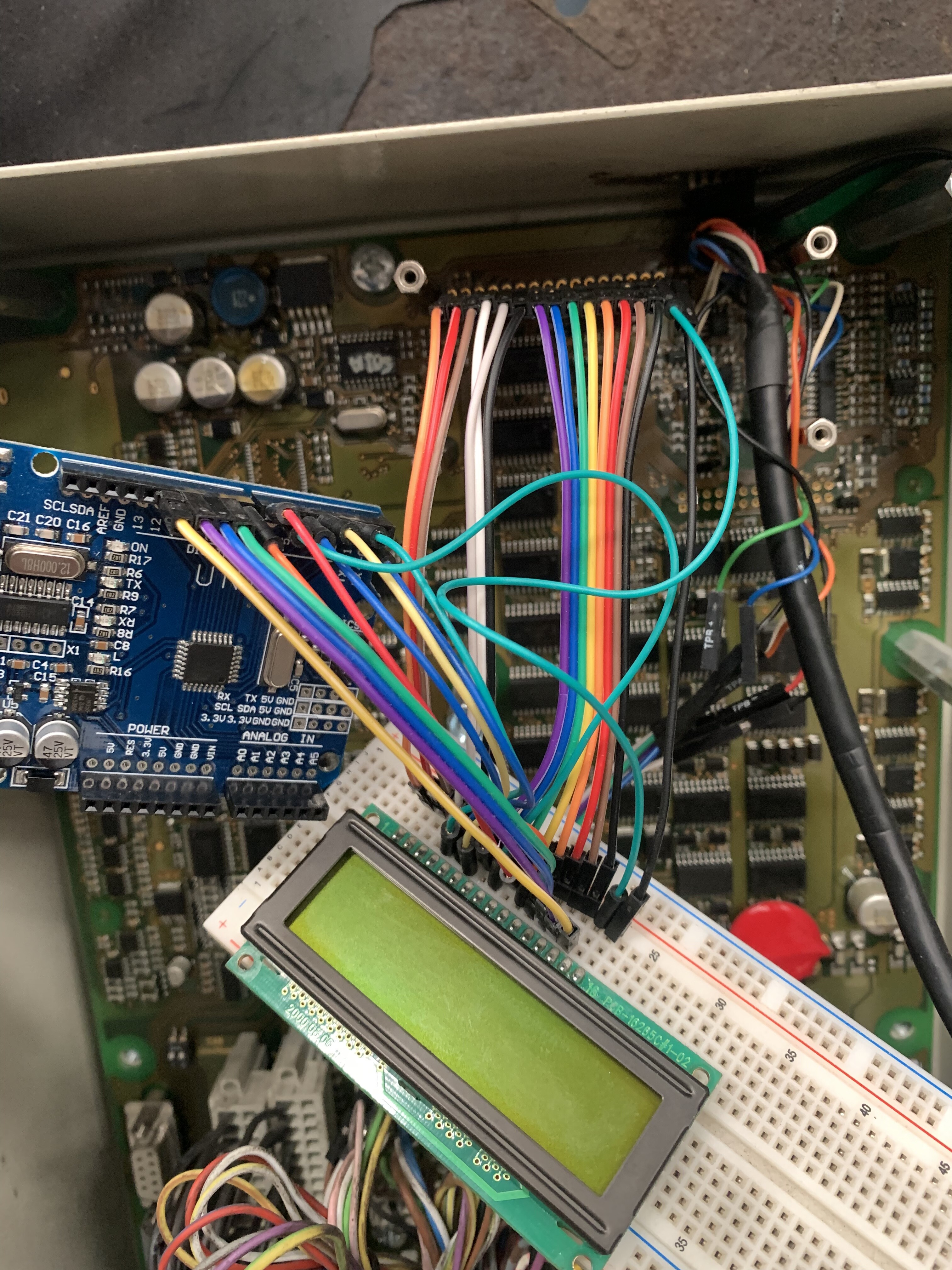
Can you show a quality still picture of the underside of the LCD display and the wiring to it, both your wiring and the original wiring ?
But, in principle it looks relatively simple and I'll see what I can do to help get this working.
EDIT
What Arduino board are you running this on and, if it is not an 8bit Nano/Uno etc., did you get any compiler warnings ?
I’m using arduino uno. There is no warnings


I didn’t connect ground. Arduino is powered with usb from PC and LCD is powered from LCD
Now I checked and LCD is working with 5V from PLC.
First I connect arduino directly where LCD is connected. Like it didn’t work, I used the protoboard to connect LCD and arduino in paralel so both are connected.
I tried to unplug some pins and letters in LCD become odd letters, but I had an “error during monitoring” from PLC too. I don’t know why, maybe PLC receive some information from LCD
The GND of the Uno must be connected to the GND of the circuit board under test say taken at pin 1 of the LCD.