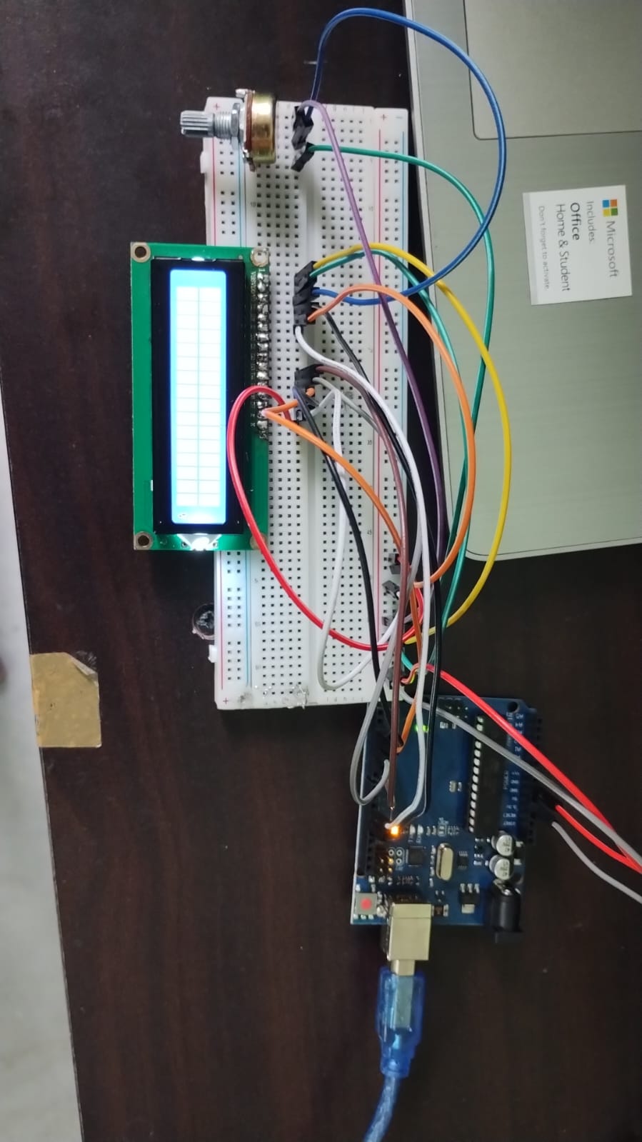
Hey everyone, myself Pranav, an Arduino beginner. I was working with an 1602 LCD screen. I had soldered it all by myself (no experience in professional soldering) and the pins were a little up and down when I soldered it. So I had done some mess and somehow removed the solder and fixed it and then soldered it again and when I made the circuit and put the Arduino, it showed white squares. While plugged into the circuit, I did some soldering stuff and it didn't work. When I put all the pins as it is from the code that I had written into another code from google, it showed me an error that semi colon was missing. so when I fixed it in my main code, it worked. But now it's been 2-3 months and when I again made the circuit the lcd screen shows white squares only. I did some soldering stuff again while using the code from google (the one that i used last time) but that showed me some random characters on the screen. Even I tried using the code that I had written and used it last time which was working fine with the lcd. Help is appreciated. And below ive attached the video when the lcd screen was working.
I tried rechanging the circuits but that ain't helping
(here is the link to the video when the lcd was working)
[Video when LCD was Working] (https://drive.google.com/file/d/12tn2InCSlExx4qXRaUtUhaJ4-ye4F3VH/view?usp=sharing)
I know that the soldering is bad, but it was like this only the last time also
(my code)
#include <LiquidCrystal.h>

// Guide for LCD without i2c (https://github.com/proshenjitenv48/Connect-an-LCD-to-an-Arduino-without-using-an-I2C-module)

// initialize the library by associating any needed LCD interface pin
// with the arduino pin number it is connected to
const int rs = 12, en = 11, d4 = 5, d5 = 4, d6 = 3, d7 = 2;
LiquidCrystal lcd(rs, en, d4, d5, d6, d7);

void setup() {
  lcd.begin(16, 2);
  lcd.print("Hello World!");
}

void loop() {

}
(the code from google)
#include <LiquidCrystal.h>

char array1[]="     QuadStore   ";                //the string to print on the LCD
char array2[]="  hello geeks!                ";  //the string to print on the LCD
char array3[]=" www.quadstore.in ";                //the string to print on the LCD

int tim = 250;  //the value of delay time

// initialize the library with the numbers of the interface pins
const int rs = 12, en = 11, d4 = 5, d5 = 4, d6 = 3, d7 = 2; //the code for pins initialization which I had directly imported from my code
LiquidCrystal lcd(rs, en, d4, d5, d6, d7);

void setup()
{
  lcd.begin(16, 2);  // set up the LCD's number of columns and rows:
}

void loop()
{
    lcd.clear();  //Clears the LCD screen and positions the cursor in the upper-left corner
    lcd.setCursor(15,0);                   // set the cursor to column 15, line 1
    for (int positionCounter2 = 0; positionCounter2 < 30; positionCounter2++)
    {
      lcd.scrollDisplayLeft();             //Scrolls the contents of the display one space to the left.
      lcd.print(array2[positionCounter2]); // Print a message to the LCD.
      delay(tim);                          //wait for 250 microseconds
    }

    lcd.clear();  //Clears the LCD screen and positions the cursor in the upper-left corner.

    lcd.setCursor(0,0);                    // set the cursor to column 15, line 0
    for (int positionCounter1 = 0; positionCounter1 < 16; positionCounter1++)
    {
      lcd.print(array1[positionCounter1]); // Print a message to the LCD.
      delay(tim);                          //wait for 250 microseconds
    }

    lcd.setCursor(0,1);                    // set the cursor to column 15, line 1
    for (int positionCounter3 = 0; positionCounter3 < 16; positionCounter3++)
    {
      lcd.print(array3[positionCounter3]); // Print a message to the LCD.
      delay(tim);                          //wait for 250 microseconds
    }
}