Hi everybody,
According to this specs https://www.sparkfun.com/datasheets/LCD/GDM1602K-Extended.pdf maximum supply current is 2.5mA.. Does that include the current draw when back-light is connected ?
Does that include the current draw when back-light is connected ?
No.
Don
floresta:
Does that include the current draw when back-light is connected ?
No.
Don
Ok so how much is the back-light current ? at least approximately ?
I have a 'non-extended' (one page) version of the data sheet which gives more information about the backlight. It indicates that the typical operating current is 120 mA and the maximum is 160 mA.
Note that it is your responsibility to assure that there is enough resistance in series with the LED to limit the current to these values. There may be a resistor on your pc board or you may have to add one externally.
Don
floresta:
I have a 'non-extended' (one page) version of the data sheet which gives more information about the backlight. It indicates that the typical operating current is 120 mA and the maximum is 160 mA.Note that it is your responsibility to assure that there is enough resistance in series with the LED to limit the current to these values. There may be a resistor on your pc board or you may have to add one externally.
Don
Thanks for replying 
I will power the LCD from the arduino's 5V source, so i guess im not going to use the back-light at all...draws too much current!!!!
Best to measure the backlight current, depending on the module, these vary all over the map. Lousy datasheet, doesn't give the backlight current spec.
For example, I use these LCD modules (nice sale price right now I see) and I really like that the backlight only needs 15mA @ 5V. This means I can drive them from a PWM pin and vary the brightness.
Edit: Here is an alternate datasheet, it says backlight requires 120mA typ, 160mA max. It says "LED" but it also says "EL", so I suspect the backlight is really electroluminescent.
zaxarias:
I will power the LCD from the Arduino's 5V source, so i guess I'm not going to use the back-light at all...draws too much current!!!!
You'll be sorry!
Most of these units draw about 20 mA or so, I just went and measured it - about 151 mV across the "101" - 100 ohm resistor R8 on the one next to me which would be 150 mA but the USB supply is loaded down to 4.55V by all the junk I have connected. Which means you can probably control it directly from an Arduino pin.
There will be some that are entirely different, but I refer to the common $2.50 devices. Just check R8 - if it is "101", then 20 mA will be pretty much it.
R7 on the one Jack cites - I can make it out as probably "101". What do you measure across it,Jack?
Edit: Here is an alternate datasheet, it says backlight requires 120mA typ, 160mA max.
Why didn't I mention those values? Oh - I did.
Don
Most of these units draw about 20 mA or so, I just went and measured it - about 151 mV across the "101" - 100 ohm resistor R8 on the one next to me which would be 150 mA but the USB supply is loaded down to 4.55V by all the junk I have connected. Which means you can probably control it directly from an Arduino pin.
This agrees with my experience as well.
When you do the math with the numbers that I (and Jack) supplied you will find out that the required resistance to give the nomnal current is in the order of 7 ohms. Since most of us use a much larger resistor, typically at least 100 ohms (as on the board investigated by Paul) the actual LED current is much lower than that mentioned in the datasheet and the backlight is still quite bright. You should have no trouble powering it directly from the Arduino.
Don
It seems the best solution is to measure the current draw using a multimeter...
Edit: floresta i believei wont have trouble too, i just dont want to push my arduino to the limits..
floresta:
Edit: Here is an alternate datasheet, it says backlight requires 120mA typ, 160mA max.
Why didn't I mention those values? Oh - I did.
Don
A thousand apologies, my bad for reading too quickly
A thousand apologies, my bad for reading too quickly
I do that frequently as well.
Getting back to your original post:
It says "LED" but it also says "EL", so I suspect the backlight is really electroluminescent.
If you look at the diagrams at the top of the page it appears that there are several different versions, LED backlight, EL backlight, and no backlight..
Don
i measured the back-light. it's 40mA at approximately 4V..
Would be interested in a photo of your actual display. Always nice to know what different things are around.
What is the value of R7 or R8 in series with the LED?
Paul__B:
Would be interested in a photo of your actual display. Always nice to know what different things are around.What is the value of R7 or R8 in series with the LED?
This is the LCD i used, you don't see it working because something went wrong and some pixels were lost... 8) 8)
When i tried to measure the current , i used pins 15(3.3V)-16(GND), i saw no back-light and except of that LCD turned off.. I took off the wires and opened the LCD again, i had some pixels missing.. I don't think i made anything wrong to the wiring(just two wires needed for the back light).. Then i saw those "A" and "K" one the right side, guess what, i used "A" for 3.3V and "K" for Ground, the back light was on and everything was working fine(except the lost pixels :D).. I really don't know what cause the LCD to malfunction, i just wont try to power the back light through pins 15-16..
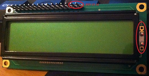
Having some difficulty making sense of what you have been doing here.
zaxarias:
When I tried to measure the current , I used pins 15(3.3V)-16(GND), i saw no back-light and except of that LCD turned off.
If you were applying 3.3V to the backlight, it probably will not light at all. That would be very close to the threshold voltage of the white LED.
zaxarias:
Then i saw those "A" and "K" one the right side, guess what, I used "A" for 3.3V and "K" for Ground, the back light was on and everything was working fine(except the lost pixels. I really don't know what cause the LCD to malfunction, I just wont try to power the back light through pins 15-16.
If you connect to those "A" and "K" pins, you are bypassing the current limiting resistor(s). That is not sensible. It may well light as you suggest, at something just over 3.3V, but you are not regulating the current, and 40mA is probably excessive when you apply 4V directly to the LED terminals.
Why do you keep referring to 3.3V if this is a 5V device? If the resistors (which are on the other side of the board) are as I suggested, then ground to pin 16 and 5V to pin 15 should light the LED at about 15 mA. By the way, you generally cannot measure the current with an ordinary multimeter on the 200mA range; you have to measure the voltage across the resistor on the board and calculate the current by knowing its resistance.
Of course pins 15 and 16 for the backlight have absolutely nothing whatsoever to do with the LCD panel and its operation. What voltage are you powering it with?
Paul__B:
Why do you keep referring to 3.3V if this is a 5V device? If the resistors (which are on the other side of the board) are as I suggested, then ground to pin 16 and 5V to pin 15 should light the LED at about 15 mA. By the way, you generally cannot measure the current with an ordinary multimeter on the 200mA range; you have to measure the voltage across the resistor on the board and calculate the current by knowing its resistance.
As you can see in the datasheet https://www.sparkfun.com/datasheets/LCD/GDM1602K-Extended.pdf this LCD needs an input voltage between 4.7-5.5V Max. However it's not the same for the back light which has a maximum of 4.6V.. That's why i didn't supplied the back light with 5V as you say!!!! As i told before the LCD turned off when tried to power the back light through pins 15-16.. The wiring was OK, the pin headers are OK, there is no continuity between those pins...
Of course pins 15 and 16 for the back light have absolutely nothing whatsoever to do with the LCD panel and its operation. What voltage are you powering it with?
LCD 5V, Back light never lighted through pins 15-16, instead it destroyed some pixels.. Back light was ok through A and K on 3.3V and about 4V(external power source)...
However it's not the same for the back light which has a maximum of 4.6V.
You don't really understand the datasheet. The voltage to which you refer is not a rating, it is a characteristic.
You do not apply a specific voltage to an LED, instead you apply enough voltage to get it to function and then you limit the current to its rated value, typically with a series resistor.
When the current through the LED has been limited to the proper value you can then measure the voltage across the LED and it should be somewhat near the value in the datasheet.
LCD 5V, Back light never lighted through pins 15-16, instead it destroyed some pixels.. Back light was ok through A and K on 3.3V and about 4V(external power source)...
You may have damaged the backlight by applying a non current limited voltage directly to the A and K backlight pins but the destruction of any pixels is unrelated - unless you inadvertently applied the voltage elsewhere as well.
Don
floresta:
However it's not the same for the back light which has a maximum of 4.6V.
You don't really understand the datasheet. The voltage to which you refer is not a rating, it is a characteristic.
You do not apply a specific voltage to an LED, instead you apply enough voltage to get it to function and then you limit the current to its rated value, typically with a series resistor.
When the current through the LED has been limited to the proper value you can then measure the voltage across the LED and it should be somewhat near the value in the datasheet.
LCD 5V, Back light never lighted through pins 15-16, instead it destroyed some pixels.. Back light was ok through A and K on 3.3V and about 4V(external power source)...
You may have damaged the backlight by applying a non current limited voltage directly to the A and K backlight pins but the destruction of any pixels is unrelated - unless you inadvertently applied the voltage elsewhere as well.
Don
Thanks for replying, however let me believe that i do understand the datasheet (I think you didn't look at it !!!)
I never said i should apply a certain voltage, i just said what is thew maximum voltage for the back light to operate according to the data sheet !!! And according to the datasheet the back light voltage should not be more than 4.6V .. 
Limit the current to it's rated value ? The datasheet doesn't mention any current rating for the back light!!!
I did not damage the back light, i never even mentioned something like that  , and i didn't apply a voltage else where(if you looked my previous posts you will see that i checked the wiring again, the pin headers and any possible unreasonable continuity between pins..Everything was as it should be !!!).. Also , something i didn't say before, i tried twice to turn on the back light ,at 4V, by pins 15-16 and nothing happened!!!! perhaps it was meant to malfunction !!!
i just said what is thew maximum voltage for the back light to operate according to the data sheet !!!
You still don't understand the difference between a 'rating' and a 'characteristic'.
Once again, the 4.6 volts is not the maximum voltage that you can or should apply to the LED. Rather, it is the maximum voltage drop that will appear across any of this type of LED when it is operating within it's ratings.
If you have a box full of these devices and you measure the voltage across each of their backlight LEDs when they are operating within their ratings you can expect to measure a wide range of voltages, but none of them should be more than 4.6 volts.
What this actually means is that when you are selecting a power source you must make sure that it delivers more than 4.6 volts if you want to be certain that you can get every backlight to function.
The datasheet doesn't mention any current rating for the back light!!!
Did you look at reply #3 or #5?
Also , something i didn't say before, i tried twice to turn on the back light ,at 4V, by pins 15-16 and nothing happened!!!!
Because, as explained above, you must use a supply greater than 4.6 volts (with a current limiting resistor) to be sure to be able to get the LED to conduct.
Don