LCD display with ILI9341 driver on Arduino

Feddar:
Can the touch (XPT2046) be operated using SPI? (ie CLK-CLK, DIN-MOSI, DO-MISO, CS-SS). I am trying to use the new URTouch library.

SPI is possible but the XPT2046 transactions are 12 bit which AVR processors (UNO etc) do not natively handle (hardware is 8 bit based). So most touch libraries use a slower bit bash serial protocol which is not much hassle and the slowness is not a problem as a lot of time is used up checking/verifying/debouncing touches by filtering x,y values anyway.

I am not familiar with the URTouch library so cannot help there.

Oh, thanks for the info. Would you be so kind to let me know which touch library you would recommend? I am leaning towards using ILI9341_due for the screen itself. I have other SPI working at the same time as well.

hey everyone,

I am recently working on a 2.8 tft 240*320 with only spi interface. I tried to use library adafruit ili9341 but it is not working. the information of the serial monitor is shown in the attachment. Does any body know what the problem is and how to solve it? Thank you very much

Capture.JPG

Capture2.JPG

Why do we need the 4050 chip? There's a 3.3V line on the Arduino!

Level shifting of IO lines, Not Power supply.

Thanks.

What is the purpose of MISO for these LCDs?

Reading the GRAM memory.
Reading the ID.
Reading the Status registers.
...

David.

david_prentice:
Reading the GRAM memory.
Reading the ID.
Reading the Status registers.
...

David.

What might be an application of reading GRAM memory? Isn't this the same as what is being sent to the LCD?

Reading ID - i.e. this tells the Arduino which slave a particular device is?

Status registers are like error codes?


I got everything connected up according to the attached diagram... so I fixed the ground and connected the MISO directly into the Arduino.

I used the standard drawtext example in the ili9341 library

/*  draw text's APP
    drawChar(INT8U ascii,INT16U poX, INT16U poY,INT16U size, INT16U fgcolor);
    drawString(char *string,INT16U poX, INT16U poY,INT16U size,INT16U fgcolor);
*/

#include <stdint.h>
#include <TFTv2.h>
#include <SPI.h>

void setup()
{
    TFT_BL_ON;      // turn on the background light
    Tft.TFTinit();  // init TFT library
    
    Tft.drawChar('S',0,0,1,RED);                // draw char: 'S', (0, 0), size: 1, color: RED
    
    Tft.drawChar('E',10,10,2,BLUE);             // draw char: 'E', (10, 10), size: 2, color: BLUE
    
    Tft.drawChar('E',20,40,3,GREEN);            // draw char: 'E', (20, 40), size: 3, color: GREEN
    
    Tft.drawChar('E',30,80,4,YELLOW);           // draw char: 'E', (30, 80), size: 4, color: YELLOW
    
    Tft.drawChar('D',40,120,4,YELLOW);          // draw char: 'D', (40, 120), size: 4, color: YELLOW
    
    Tft.drawString("Hello",0,180,3,CYAN);       // draw string: "hello", (0, 180), size: 3, color: CYAN
    
    Tft.drawString("World!!",60,220,4,WHITE);    // draw string: "world!!", (80, 230), size: 4, color: WHITE
    

}

and...

I get nothing. The screen is completely blank.

The Arduino blinks TX and RX when I click upload but then nothing.

What am I missing? Please note, this is my second day using Arduino so very new to the scene.

You are using a 3.3V display module. It must have 3.3V logic.

The easiest way is to use series resistors. Look at Bodmer's library and "connection tutorial"

If you use a specific level shifter i.c. then you must tell it to produce 3.3V logic. Your wiring has forced 5V logic. This might have damaged your ILI9341.

I note that your module has got holes for a 5-pin header. Most of these displays have 4 holes.

In reply to your MISO question. If you do not want to read the ID, registers or display memory, you do not need to connect MISO.

It is a bit like driving a car. You don't need to have eyesight to operate the steering wheel or accelerator pedal. On the other hand, it is sometimes useful to see where you are going.

David.

david_prentice:
You are using a 3.3V display module. It must have 3.3V logic.

The easiest way is to use series resistors. Look at Bodmer's library and "connection tutorial"

On some page of this thread there was a discussion regarding the downsides to using resistors for this job... I think it might have been more related to the SD card slot, but I decided to go the 4050 route for the display itself anyway.

david_prentice:
If you use a specific level shifter i.c. then you must tell it to produce 3.3V logic. Your wiring has forced 5V logic. This might have damaged your ILI9341.

A bit confused how my wiring has caused it to produce 5V logic?

I tested all voltages, into and out of the chip, everything is as expected, power is 3.3V, logic I/O are 5V on the input side and are 3.3V on the output.

david_prentice:
I note that your module has got holes for a 5-pin header. Most of these displays have 4 holes.

I checked all the pins on the other side to which I have attached all my wires to, they are identical to the other units that were mentioned in the thread.


I did some further testing here is where things get a bit bizzare.

I made the following code:

/*  draw text's APP
    drawChar(INT8U ascii,INT16U poX, INT16U poY,INT16U size, INT16U fgcolor);
    drawString(char *string,INT16U poX, INT16U poY,INT16U size,INT16U fgcolor);
*/

#include <stdint.h>
#include <TFTv2.h>
#include <SPI.h>

void setup()
{
    TFT_BL_ON;      // turn on the background light
    Tft.TFTinit();  // init TFT library
}

void loop()
{
  digitalWrite(SS, LOW);    // SS is pin 10
delay (1000);  // 1 seconds delay

    Tft.drawChar('S',0,0,1,RED);                // draw char: 'S', (0, 0), size: 1, color: RED
    
    Tft.drawChar('E',10,10,2,BLUE);             // draw char: 'E', (10, 10), size: 2, color: BLUE
    
    Tft.drawChar('E',20,40,3,GREEN);            // draw char: 'E', (20, 40), size: 3, color: GREEN
    
    Tft.drawChar('E',30,80,4,YELLOW);           // draw char: 'E', (30, 80), size: 4, color: YELLOW
    
    Tft.drawChar('D',40,120,4,YELLOW);          // draw char: 'D', (40, 120), size: 4, color: YELLOW
    
    Tft.drawString("Hello",0,180,3,CYAN);       // draw string: "hello", (0, 180), size: 3, color: CYAN
    
    Tft.drawString("World!!",60,220,4,WHITE);    // draw string: "world!!", (80, 230), size: 4, color: WHITE

  digitalWrite(SS, HIGH);    // SS is pin 10
delay (1000);  // 1 seconds delay

    Tft.drawChar('S',0,0,1,RED);                // draw char: 'S', (0, 0), size: 1, color: RED
    
    Tft.drawChar('E',10,10,2,BLUE);             // draw char: 'E', (10, 10), size: 2, color: BLUE
    
    Tft.drawChar('E',20,40,3,GREEN);            // draw char: 'E', (20, 40), size: 3, color: GREEN
    
    Tft.drawChar('E',30,80,4,YELLOW);           // draw char: 'E', (30, 80), size: 4, color: YELLOW
    
    Tft.drawChar('D',40,120,4,YELLOW);          // draw char: 'D', (40, 120), size: 4, color: YELLOW
    
    Tft.drawString("Hello",0,180,3,CYAN);       // draw string: "hello", (0, 180), size: 3, color: CYAN
    
    Tft.drawString("World!!",60,220,4,WHITE);    // draw string: "world!!", (80, 230), size: 4, color: WHITE    
}

I didn't put much thought into it... just testing the SS pin at this stage.

When I don't have the LCD plugged in, my SS output changes 0-3.3V and my input changes 0-5V as expected.

The moment I plug the LCD in, the voltage on the input continues to alternate betwee 0-5V as expected however my output pin changes from 2-3.3V, it never drops to zero. This is why my LCD never switches on. The question is why this strange behaviour?

Another question, do I need to plug a power supply into the Arduino? Maybe there isn't enough current to drive the LCD?

Also, to me, the function setup() seems to be something that shouldn't have code that actually does the drawing, logically to me you would put all the code that draws stuff in loop(). I'm a bit befuddled by the fact that all the draw commands are under setup().

A bit confused how my wiring has caused it to produce 5V logic?
Oops. My apologies. When I looked at your Fritzing, I thought that you had connected pin#1 of the CD4050 to 5V instead of 3.3V !!

So you have the electrical connections correct.

Your sketch does not show a constructor(). So I have no idea what pins you have selected or what the TFTv2 library wants.

I Googled for "TFTv2 library" and found SeeedStudio library

The source code expects TFT_CS on PORTD.5 for a Uno i.e. digital #5

Personally, I would expect people to use Adafruit_ILI9341 library as the first choice.
However there are many other ILI9341 libraries e.g. from Marek, Bodmer, ...

Of course, SeeedStudio libraries are probably absolutely fine. You just need to edit TFTv2.h to match your specific wiring. (there does not seem to be a specific constructor)

It is always wise to quote a link to any third party library you are using. It is quite possible that I have not found the official SeeedStudio repositories. The GitHub name is spelled "reeedstudio"

David.

I have tried all the libraries that can be found in this thread...

1.) Seeed (didn't modify these as you suggested I needed to... didn't know you had to... I'm no electronics or programming expert so it might take some time for me to figure out what exactly I need to modify).

2.) the library that nid69ita posted on page 2

3.) Adafruit_ILI9341

4.) Adafruit_ILI9340

None seem to work.

  1. Don´t connect TFT-MISO on MISO-Arduino (pin 12).

  2. VCC of CD4050 must be connected on 3.3V line.

The library for ILI9341@MarekB it´s an excellent choise

There are several versions of SPI ILI9341 display modules.

Most have constructors like this:

// Use hardware SPI (on Uno, #13, #12, #11) and the above for CS/DC/RST
Adafruit_ILI9341 tft = Adafruit_ILI9341(TFT_CS, TFT_DC, TFT_RST);

Note that the Adafruit examples omit the TFT_RST argument. Because the Adafruit boards have a hardware pullup on the TFT_RESET pin.

The Red modules from Ebay do not have a pullup resistor on TFT_RESET. So you must connect it to the Arduino. And you must configure it in the constructor.
In your case, you would use:

// Use hardware SPI (on Uno, #13, #12, #11) and the above for CS/DC/RST
Adafruit_ILI9341 tft = Adafruit_ILI9341(10, 9, 8);

If you are using the TFTv2 library from my link you would need to re-wire your breadboard.

TFT_RST to digital #7  //the library expects a Backlight but it will perform the RESET function
TFT_DC   to digital #6
TFT_CS   to digital #5

I suggest that you make an adapter shield like TFTLCDCyg. It ensures your TFT projects are electrically and mechanically correct. You can wire the SD card onto the same hardware SPI bus as your TFT. And use the spare channel on your 4050 for SD_CS.

If you use the ILI9341 modules with an XPT2046 Touch controller, you need a channel for the TS_CS line. You could steal the TFT_RESET channel if you provide an external pullup resistor on the TFT_RST pin.

David.

TFTLCDCyg:

  1. Don´t connect TFT-MISO on MISO-Arduino (pin 12).

Tried not connecting it, no change. I don't think it's hurting anything if it's connected even if it's not being used. Might as well connect all the pins. Maybe in future I'll have some use for it like transferring a screenshot or something.

TFTLCDCyg:
2. VCC of CD4050 must be connected on 3.3V line.

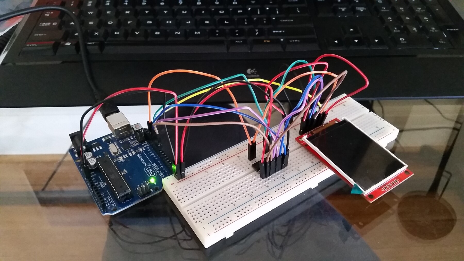
Yep, as per my diagram, 3.3V.

TFTLCDCyg:
The library for ILI9341@MarekB it´s an excellent choise

D/l it and tested it... same result... black screen. The SS pin is at a constant 3.3V. The display is stubbornly not wanting to be sent any data.

The library looks good though, has documentation!

david_prentice:
There are several versions of SPI ILI9341 display modules.

Looks like the pins are identical if mine is slightly different. I guess the SPI interface should be the same, the only difference would be that pull up resistor that you mention further down in your post.

david_prentice:
Most have constructors like this:

// Use hardware SPI (on Uno, #13, #12, #11) and the above for CS/DC/RST

Adafruit_ILI9341 tft = Adafruit_ILI9341(TFT_CS, TFT_DC, TFT_RST);

I'm using MarekB's library now and the sketch I'm using has what you're talking about. My pins line up with the CS, DC and RST pins now. Well, they were correct, it's just that programatically, they are now defined.

/*
This sketch is demonstrating loading monochome images from a byte array.
The advantage of using monochrome images is its size. You could fit a fullscreen
monochrome image in Uno's program memory. You could not do that with
a full color image.
*/

#include "SPI.h"
#include "ILI9341_due_config.h"
#include "ILI9341_due.h"

#if defined(ARDUINO_ARCH_AVR)
#include <avr/pgmspace.h>
#elif defined(ARDUINO_SAM_DUE)
#define PROGMEM
#endif

const uint8_t arduLogo[] PROGMEM = {                                              // width 40, height 32
 B00000000, B00000000, B00000000, B00000000, B01111110,
 B00000000, B00000000, B00000000, B00000000, B00101110,
 B00000000, B00000000, B00000000, B00000000, B00101010,
 B00000001, B11111000, B00000000, B00001111, B10000000,
 B00000111, B11111110, B00000000, B00111111, B11100000,
 B00011111, B11111111, B10000000, B11111111, B11111000,
 B00111111, B00000111, B11000001, B11110000, B11111100,
 B00111100, B00000011, B11100011, B11100000, B00111100,
 B01111000, B00000000, B11110111, B10000000, B00011110,
 B01110000, B00000000, B01110111, B00000110, B00001110,
 B11100000, B00000000, B00111110, B00000110, B00000111,
 B11100001, B11111000, B00111110, B00011111, B10000111,
 B11100001, B11111000, B00011100, B00011111, B10000111,
 B11100000, B00000000, B00111110, B00000110, B00000111,
 B11110000, B00000000, B00111110, B00000110, B00001111,
 B01110000, B00000000, B01110111, B00000000, B00001110,
 B01111000, B00000000, B11110111, B10000000, B00011110,
 B00111100, B00000011, B11100011, B11100000, B00111100,
 B00111111, B00001111, B11000001, B11110000, B11111100,
 B00011111, B11111111, B00000000, B11111111, B11111000,
 B00000111, B11111100, B00000000, B00111111, B11100000,
 B00000001, B11110000, B00000000, B00001111, B10000000,
 B00000000, B00000000, B00000000, B00000000, B00000000,
 B00000000, B00000000, B00000000, B00000000, B00000000,
 B00000000, B00000000, B00000000, B00000000, B00000000,
 B01110011, B11001111, B00100010, B11100100, B01001110,
 B10001010, B00101000, B10100010, B01000100, B01010001,
 B10001010, B00101000, B10100010, B01000110, B01010001,
 B11111011, B11001000, B10100010, B01000101, B01010001,
 B10001010, B10001000, B10100010, B01000100, B11010001,
 B10001010, B01001000, B10100010, B01000100, B01010001,
 B10001010, B00101111, B00011100, B11100100, B01001110
};

// CS and DC for the LCD
#define LCD_CS 10 // Chip Select for LCD
#define LCD_DC 9 // Command/Data for LCD
#define LCD_RST 8 // Command/Data for LCD

ILI9341_due tft(LCD_CS, LCD_DC, LCD_RST);

void setup()
{
 Serial.begin(9600);
 tft.begin();
 tft.setRotation(iliRotation270); // landscape

 tft.fillScreen(ILI9341_BLACK); 

 tft.drawBitmap(arduLogo, 160, 100, 40, 32, ILI9341_DARKCYAN); // "transparent" background
 tft.drawBitmap(arduLogo, 110, 100, 40, 32, ILI9341_WHITE, ILI9341_DARKCYAN); 
}

void loop()
{

 /* add main program code here */

}

david_prentice:
Note that the Adafruit examples omit the TFT_RST argument. Because the Adafruit boards have a hardware pullup on the TFT_RESET pin.

That went a bit over my head. Did some basic reading on it, but I'll have to dig deeper to understand what pullup resistors are, what they do and whether I have it.

david_prentice:
The Red modules from Ebay do not have a pullup resistor on TFT_RESET. So you must connect it to the Arduino. And you must configure it in the constructor.
In your case, you would use:

// Use hardware SPI (on Uno, #13, #12, #11) and the above for CS/DC/RST

Adafruit_ILI9341 tft = Adafruit_ILI9341(10, 9, 8);

Yep the new sketch has this now. (lib is here ILI9341_due).

david_prentice:
You can wire the SD card onto the same hardware SPI bus as your TFT. And use the spare channel on your 4050 for SD_CS.

If you use the ILI9341 modules with an XPT2046 Touch controller, you need a channel for the TS_CS line. You could steal the TFT_RESET channel if you provide an external pullup resistor on the TFT_RST pin.

David.

Don't plan on using the SD slot nor is my unit touch, just interested in graphical output at this stage.

Correct me if I'm wrong since this is my first Arduino project, I add the library under sketch->include library.

Then I simply open the example sketch in the library examples folder and simply click, upload?

I don't need to compile the library .cpp and .h files?

Using this new example sketch, as I mentioned, I get 3.3V output from the 4050 SS pin.

I've actually got a couple of these units, I plugged in a different one (same version I think), same result. Nadda.

Your Fritzing looks clear. The connections look fine to me.

Providing your constructor() is accurate, Marek's ILI9341_due.h, Bodmer's TFT_ILI9341.h, Adafruit's Adafruit_ILI9341.h, ... should all work.

In fact most of these libraries will make some form of diagnostic report on the Serial Terminal. (you need to connect MISO line to #12. you do not need the 4050)

David.

@Atomic_Sheep

Have you identified pin 1 correctly and plugged the 4050 in the correct way around?

Is the backlight LED working? If it is, you should see some white light leaking out around the edges of the display.

david_prentice:
In fact most of these libraries will make some form of diagnostic report on the Serial Terminal. (you need to connect MISO line to #12. you do not need the 4050)

Will have to look into this.

bodmer:
@Atomic_Sheep

Have you identified pin 1 correctly and plugged the 4050 in the correct way around?

Yer pretty sure I'm right in this department.

Pin 1 is bottom right with the red cable.

bodmer:
Is the backlight LED working? If it is, you should see some white light leaking out around the edges of the display.

No the unit is completely blank.

Bought one of those Logic Level converter modules from Arduino.

https://www.jaycar.com.au/arduino-compatible-logic-level-converter-module/p/XC4486

Maybe there's something wrong with my 4050. I'll use it for the SS signal... see how I go.

Try this wiring

Constructor for the ILI9341_due library:

#define TFT_RST 8
#define TFT_DC 9
#define TFT_CS 10
ILI9341_due tft = ILI9341_due(TFT_CS, TFT_DC, TFT_RST);

Figured it out :), I flipped an already flipped cable diagram, had my LCD connected back to front.

OOOOH I get it, so the SPI connections down one side are for the LCD and on the side for the SD reader?