xcastelo:
well, in mine there is a voltage regulator to get 3.3v from 5v power supply. But also there are a jumper to do a bridge from Vcc to 3.3v bus trace. In my case both supplies are correct. What is confusing in ebay shops is that they indicate 5 and 3.3v compatibility and one can imagine that it is the same for the serial interface pins, but really not...
Is it the same as this board? (And if so, I presume you refer to jumper J1? To clarify; must I supply 5v if the jumper is not present?)
I'm seeking a little help here with the level convertors. I have on hand some 74HC245 transceivers, they have been used in other projects here but I've never gotten around to actually using them. They are just buffers, the same as the CD4050 used here, but have an extra couple of pins, which I can't figure out despite spending some quality time with the spec sheet. I've had a good look at the diagram on page one of this thread, the buffers in the 245 are of the same kind, non-inverting, I believe, and this should be straightforward except for the extra pins (to/from voltage ?) on the 245. Its datasheet is at http://www.nxp.com/documents/data_sheet/74HC_HCT245.pdf
I'm using the same expected setup everyone is I think, one of the ILI9341 displays and a 5V Uno.
EDIT: I have the 20 pin version, just discovered there's a 24 pin version as well
I´d like to tell everybody how I have done it, maybe it will help:
I had a arduino mini pro 5V, a 5 Channel voltage regulator 5V->3V and the Display, got it from somewhere really cheap with no documentation. I tried so much, but what gave me the start was this setup:
Posted by nid69ita:
nid69ita:
D4 : RESET
D5 : CS
D6 : D/C
D7 : LED -> wired to the VCC of display , not to pin on arduino
D11 : MOSI
D12 : MISO
D13 : SCK
Downloaded the ili9341.rar from that post. Uploeaded the text-example from that lib. I have put Display Vcc and Gnd through voltage regulator (one way), then D4,CS,D/C,SCK through the 4 Channels (bidirectional) of the voltage regulator. MISO was dirctly wired. I wired MOSI directly too (because I didn´t have more channels), resulting in a white screen, I messured a bit, then took a 1kOhms resistor for that, something scrambled showed up, I tried some lower resistors and ended by a 470 Ohms resistor in the MOSI wire.... And hello world.
I just ordered a 4050 to make a little shield. I need by VR for other projects.
Ok , next problem. I can´t get the SD-Card reader to work with the tftbmp example from the ili9341 library, when I start it, it says "failed" in the serial monitor. Did someone get this working, MOSI is connected with a resistor to Pin 12, the card is a 512MB with FAT, I copied the .bmp-files on it in root directory. All other examples work fine.
Dear friends.
I'm lost with ARDUINO 256r3, not that pin works the library, as I connect it to TFT ILI9341 2.2" SPI. Where they connect or connect pin, CS, D/C and RESET? Than You
pcactiva:
Dear friends.
I'm lost with ARDUINO 256r3, not that pin works the library, as I connect it to TFT ILI9341 2.2" SPI. Where they connect or connect pin, CS, D/C and RESET? Than You
CS=> PE3=>5
DC=>PH3=>6
BK=>PH4=>7
RST=>PD4=>??? this is not connected, pin 4 is PG5
I think it is an error because PIN 4 of Mega is physical PG5 !!!
Try modify this two line for the Mega in the .h file so RST in on pin 4: #define TFT_RST_OFF {DDRG |= 0x20;PORTG |= 0x20;} #define TFT_RST_ON {DDRG |= 0x20;PORTG &=~ 0x20;}
You can also check "physical MCU pin" versus "board pin number" reading the file pin_boards.h under this folders (on my pc):
mega -> H:\arduino-IDE\hardware\arduino\variants\mega
uno -> H:\arduino-IDE\hardware\arduino\variants\standard
Right, I'm at my wits end with this. I'm starting to suspect that I may have a bum/blown up ILI9341 and would very much appreciate any help anyone can offer.
I'm now using nid69ita's ili9341.rar examples from reply #18. I'm just getting a white screen on any of them.
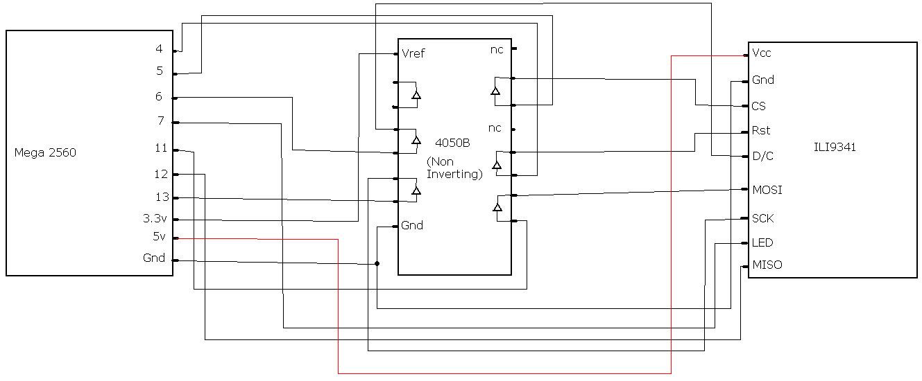
I have electrically tested and can confirm all outputs from my Mega 2560 and 4050B hex buffer are working and reaching the ILI9341 as expected.
I have tried two power connection methods, supplying 3.3V and 5V to Vcc on the ILI9341. The Mega 2560 is powered via my PC's USB.
Attached are diagrams of both power schematics I've tried and a photo of my setup. I apologise in advance for any damage they may cause to your eyes or psychology!
I think you are wrong about powering. I think you need to use 3.3V from Mega to ILI (as your schema) but also you must use 3.3V from Mega to CD4050.
I learned this watching this tutoria from Adafruit, about a LCD Nokia 5110 and a CD4050.
And the library in the rar file I think is wrong for macro about Mega pin definition as I written in previous post (about RST pin)
THe Vcc to the CD4050BE should be the 3V3 supply from the Mega and you 'should' put at least a 47uF cap across it... there's only a 1 uF MLM SMD capacitor (C14) on the Arduino board.. as the 3V3 'source apparently was only intended as a reference for changing the board from USB to DC IN Power the black PSU connector... BTW I've found that a 7.5V DC Switcher wall wart works with least heating under an 400 mA full load... Not great but 1/2 of the wasted heat of an equivalent 9V wall wart... .6 Vs 1.2 W heat produced
A couple of questions, if I may, this is getting complicated, with a few threads going on. From my reading I'm still unclear on a few things:
Mine is the same as everyone elses I think, with the penguin on the display pic. Even though that description says 5V is OK, I take it that it is not, and I should use a 4050? Mine is a BP not a BE, will that matter?
There are three libraries (at least), the seeed V2 one, the one on gmtii's git and UTFT. Any clear distinction?
What does it mean to say use the VCC from the board? Where is that accessible, the 3V3 I'd imagine comes from the output on the Uno (Leo etc).
The MISO line is data coming from the Arduino and going to the display? So, the MOSI line, data coming from the display, going to the Arduino, need not be connected, there won't be anything to send?
I'm also a little confused abou the wiring. I know there's a diagram showing a 4050 in use, but it's very hard to interpret.
I just measured the voltages on the onboard voltage regulator and it IS dropping Vcc down to 3.0V when 5V is connected to Vcc It's probably saving everybody's screens from releasing magic smoke.
(It also drops the voltage to 3.0 when I connect 3.3V to Vcc so it must be be an LDO with less than 0.3V dropout)
So...the problem is only with the data lines. I bet I could get it to work at 5V with just a few resistors. I don't know if it would need a voltage divider pair for each pin or just a single resistor.
The LED backlight supply pin would also need a resistor. The datasheet says 15mA per LED and there's 4 of them so that's 60mA total. A 33 Ohm resistor should do the trick.
...also me I have problem to connect these LCD but I have read into ebay http://www.ebay.es/itm/200952295233?ssPageName=STRK:MEWNX:IT&_trksid=p3984.m1439.l2649 that the IC is ILI9340C but the library downloaded is for ILI9341
After I have notice that my LCD board is 1580005661C but ebay product have a different code Welcome bestrepairtool.com - BlueHost.com
I have also runned the last example of ILI9341 name TFTBMP and serial terminal inform me that the id code isn't correct:
Read TFT ID failed, ID should be 0x09341, but read ID = 0x000
failed!
=(
gibo65:
...also me I have problem to connect these LCD but I have read into ebay http://www.ebay.es/itm/200952295233?ssPageName=STRK:MEWNX:IT&_trksid=p3984.m1439.l2649 that the IC is ILI9340C but the library downloaded is for ILI9341
After I have notice that my LCD board is 1580005661C but ebay product have a different code http://www.bestrepairtool.com/images/ebay/e/E019-04.jpg
I have also runned the last example of ILI9341 name TFTBMP and serial terminal inform me that the id code isn't correct:
Read TFT ID failed, ID should be 0x09341, but read ID = 0x000
failed!
=(


