LCD, LED, and Buzzer Regularly Triggered When Not Intended To

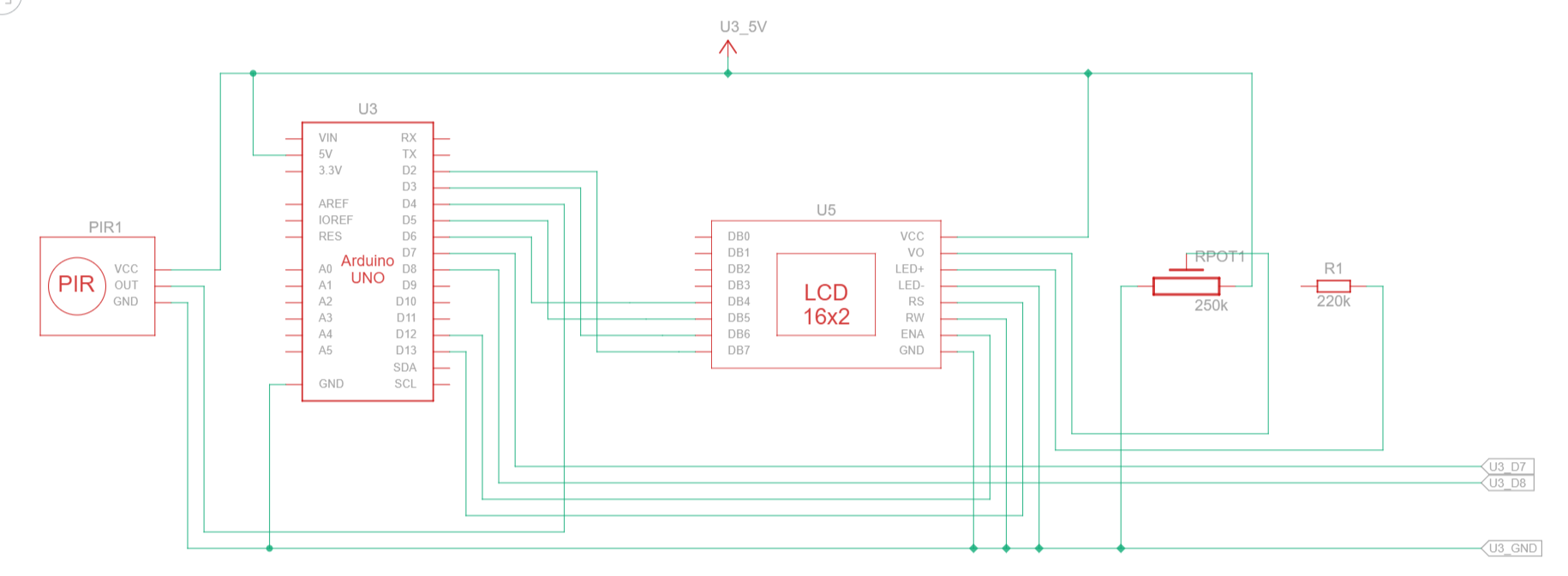
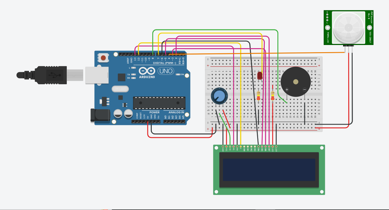
I am making a security motion detection system with an Arduino Uno R3 and a PIR sensor for my final school project (PYP), and when motion is detected, the LED and buzzer are supposed to do their own things, and the LCD is supposed to show an alert. I inserted the following code in the IDE and simulated the circuit in TinkerCAD successfully (schematic and diagram below):

#include <LiquidCrystal.h>
LiquidCrystal lcd(13, 12, 6, 5, 3, 2);
int led = 7;
int PIR = 4;
int buzzer = 8;
int PIRstatus;

void setup() {
  lcd.begin(16, 2);
  pinMode(led, OUTPUT);
  pinMode(buzzer, OUTPUT);
  pinMode(PIR, INPUT);
  lcd.clear();
}

void loop() {
  PIRstatus = digitalRead(PIR);
  if (PIRstatus == HIGH) {
    lcd.clear();
    digitalWrite(led, HIGH);
    digitalWrite(buzzer, HIGH);
    tone(buzzer, 200, 2000);  //tone(pin, frequency, Duration
    lcd.setCursor(0, 1);
    lcd.print("ALERT! CRIME!");
    delay(6000);
    lcd.clear();
  } else {
    lcd.setCursor(0, 0);
    lcd.print("SECURE");
    digitalWrite(led, LOW);
    digitalWrite(buzzer, LOW);
  }
  delay(1000);
}


I've already made sure to do everything precisely. However, when I uploaded the code and plugged the Arduino into my computer, the LED, piezo buzzer, and LCD just followed the code even if no motion was detected. I can confirm that they are not dependent on the PIR sensor for some reason because I disconnected the PIR sensor, yet the Arduino kept on reading HIGH.

Any advice or support offered is greatly appreciated, and I'm sorry if my question is probably relatively simpler compared to other topics, as I am still very new in all this technological hardware stuff. If a picture of the actual circuit is needed, I'm able to take a photo and send it. Once again, thank you.

Could you please show a photograph that clearly shows how you have everything connected?


Your LCD has an i2c backpack, but you connected it like it doesn't have that. Not sure how well that will work, but why do it anyway? Connect the LCD properly (meaning via i2c) and change your code accordingly.

Do that, and you will need only 4 wires connected to the LCD instead of 12, and you won't need the potentiometer or the resistor for the backlight, because the backpack has those built in.

The 4 wires connect from the 4 pins that stick out sideways from the backpack and should be connected to 5V, GND, and the SCL & SDA pins on the Uno.

Your LCD screen appears to have an I2C backpack and your schematic appears to show a screen without such a backpack. You cannot use an LCD screen with a soldered on backpack as a normal LCD screen (even if the pins are somehow broken out). Also the 220K resistor in series with the backlight of the screen is far too high (and appears unconnected).

Have you used the Serial Monitor ?
You need to check the PIR sensor, just the PIR sensor.
Some PIR sensors are active low, some have a 3.3V output. Sometimes I cheat a little by using INPUT_PULLUP to lift the output signal a little more.

Do you have a multimeter ? To check the output pin of the PIR sensor ?

You could use this test:

int PIR = 4;

void setup() 
{
  Serial.begin(9600);
  Serial.println("Testing the PIR sensor");
  pinMode(PIR, INPUT_PULLUP);  // INPUT_PULLUP to help the signal high level
}

void loop() 
{
  int PIRstatus = digitalRead(PIR);
  Serial.print(PIRstatus);
  delay(300);
}

Try to activate the PIR sensor and check Serial Monitor. Turn the potentiometers on the PIR sensor module to get short delays.

1 Like

It won't, because there's no connection at all:

@zarakhalisha have you verified that you have connected the PIR sensor in accordance with its pinout? Can you show clear photographs of the PIR module and the white text that is next to the pins that you connected it with?
Most PIR sensor modules like yours seem to have the Output as the middle pin, but you appear to have the right-most pin (in your photo) connected to D4 on your UNO.

Also please do what @Koepel suggests and only connect the PIR sensor and verify it works. Then start adding the other components.

2 Likes

Also, the buzzer is missing from the schematic, appears to be connected the wrong way round and should really have diode reversed across it pins to reduce voltage spikes (freewheeling/flyback diode on an inductive load).
It is really best to test each component individually to ensure you can get each one working before integrating them all into one application.

Neither am I now despite having written that it won't work. If it is a standard PCF8574 backpack then the pins should be on high impedance or with a very weak pullup resistor if it is not initialized over I2C so should not interfere with the base module. The second thing is it looks like someone has gone to some extra effort to breakout the pins of the original LCD. If it is something from the school lab to support some sort of (non-simulataneous) dual use, then it will surely have been tested.

The picture is not really clear enough for me to see that.

No, they didn't. Have a look again. The Dupont connectors dangle by the stubs that poke through the I2C backpack. There's no electrical connection.

Well, it is for me.

Your project in Wokwi simulation (no need to log in):

Start the simulation, then click on the PIR sensor, then click the button "Simulate motion".

1 Like

You could well be right. If long pins were broken through then the female duPont connectors would probably be better aligned. But interesting to know would be, if such broken out pins were available, if it would still work in normal mode with a backpack in place. The first (and accepted) answer to this question microcontroller - LCD 16x2 not taking commands from MSP430FR2355 - Electrical Engineering Stack Exchange states categorically that it would not work, however, that was not proven and the actual problem turned out to be something else (lack of common ground).

This topic was automatically closed 180 days after the last reply. New replies are no longer allowed.