Hi
I am not able to get my LCD to work.
I am afraid i might had damaged the LCD during soldering.
Need help and advise from the community.
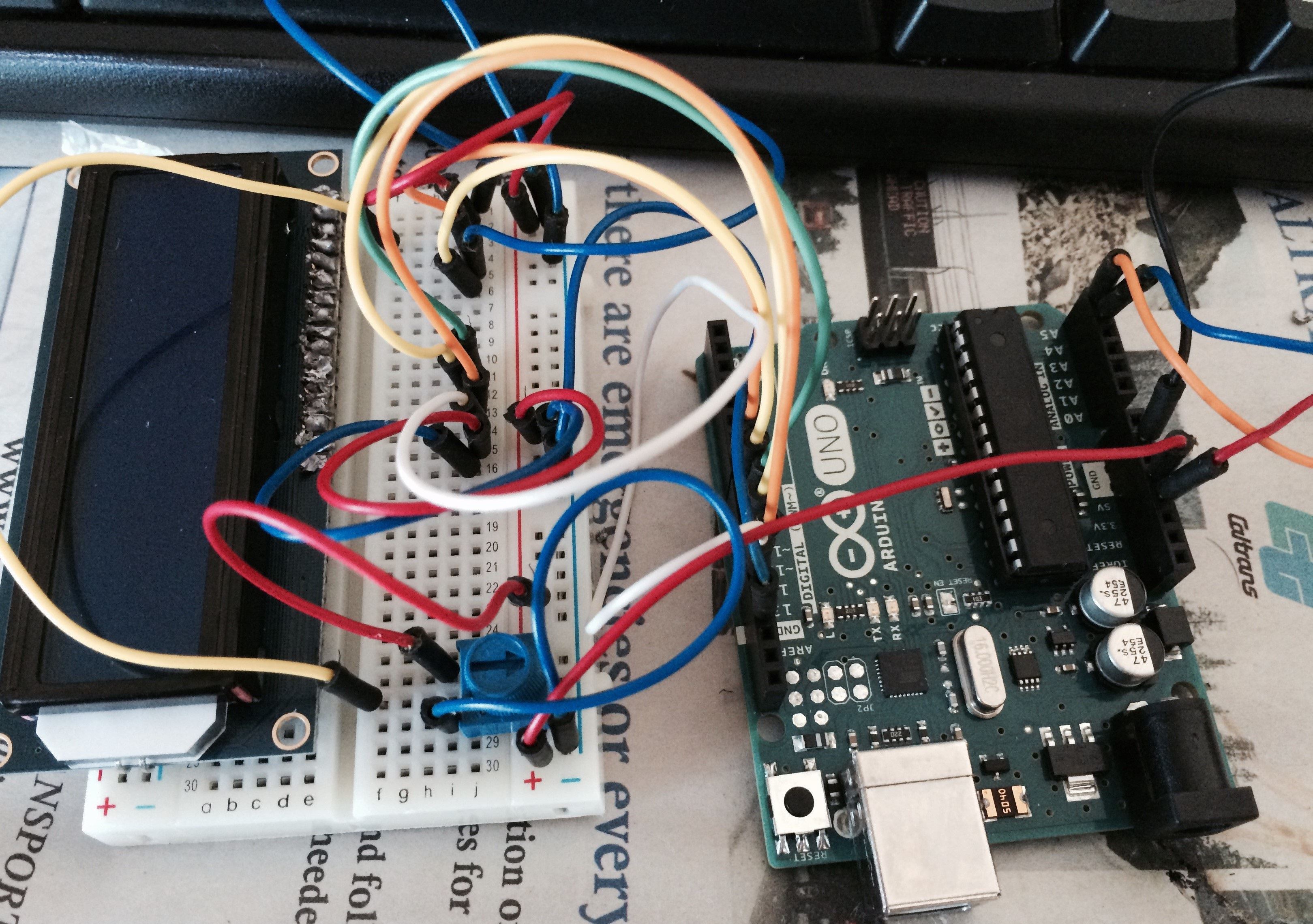
Attached is the picture of my project
Config
Arduino Uno
Adafruit Standard 16X2 LCD
Cheers
Ketant
Hi
I am not able to get my LCD to work.
I am afraid i might had damaged the LCD during soldering.
Need help and advise from the community.
Attached is the picture of my project
Config
Arduino Uno
Adafruit Standard 16X2 LCD
Cheers
Ketant
You could be right.
But ...
Did you notice that you had your display plugged into one side of the breadboard, but all the connections on the other side?
Thanks Pual and Dan... your recommendations does help alot.
now my LCD can light up but not able to display the message.
any advise ...
cheers
ketant
OK, two steps.
Take it out in daylight but not in the sun to get a fully focused picture with the camera at least a meter away vertically above, using its zoom to frame the picture.
But first, if your contrast control is correctly wired to pin 3, adjust it until you see either characters or a line of blocks. This will be with the potentiometer turned toward the grounded end. If you see neither, try again with only pins 1, 2, 3, 15 and 16 connected.
thanks Paul...
i could not get the blocks of character... how can i fix it?
Seems like you now have the contrast set to a usable value, but I cannot quite figure out the significance of that display.
»»««
We need to know what you see with only pins 1, 2, 3, 15 and 16 connected (as much as I can see, it seems to have pins 3, 15 and 16 but not 1 and 2 connected, which makes no sense). If what you show in that picture was what you get with only pins 1, 2, 3, 15 and 16 connected, then it would indicate a faulty display. If however it is the result with the Arduino connected, then it may be either a connection or code problem and we would need to see the proper daylight picture that I mentioned.
We need to see your code - included in text here but in "code" tags.
Adafruit Standard 16X2 LCD in NOT a valid specification.
How many wires have you connected to the LCD?
Does it have a SPI controller attached? ( two wire operation, but from your desorption so far, unlikely) .
With backlight working - can you see a row of character blocks on power up? You do not need any data pins connected to check this.
No software needs to be running either, just power applied to the LCD will run correct internalization to show all 16 character fields.
Is you software setup for 2 wire operation , or 4 wire data bus or 8 wire data bus?
Most LCD are pretty much bulletproof , so it is unlikely you fried something with your iron.
Likely shorted some pins at worst.
Vaclav:
Does it have a SPI controller attached? ( two wire operation, but from your desorption so far, unlikely) .
I think you need to read the previous postings - all of them - and look at the photos - poor as they are.
You are going to confuse the poor fellow with your comments - I have been working through a step-by-step procedure to determine what is, and what is not working.
Paul__B:
I think you need to read the previous postings - all of them - and look at the photos - poor as they are.You are going to confuse the poor fellow with your comments - I have been working through a step-by-step procedure to determine what is, and what is not working.
Of course you are right, what was I thinking asking all those silly confusing questions and derailing your procedure.
I suppose letting the OP to decide which procedure / recommendation / suggestion to follow is out of the question.
what was I thinking asking all those silly confusing questions
Does it have a SPI controller attached? ( two wire operation
Clock + 2×data + select = 2 wire.
I think that calibrates vaclavian arithmetic for us.