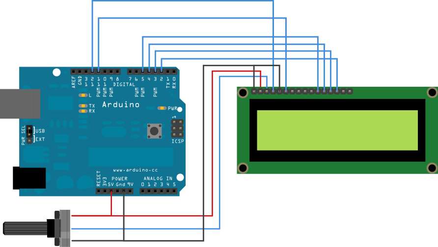
Here is a Picture of my setup.
Try to take a better picture, perhaps outside where there is more light, so that we can easily follow each of the wires.
Here is my generic step by step approach that should work:
(1) If the module has a backlight then get it working properly. This involves only pins 15 and 16 on your LCD module. Make sure to use a current limiting resistor if there is none on the LCD module.
(2) Get the power and contrast working properly. This involves only pins 1, 2, and 3 on your LCD module. You should be able to see blocks on one row of a two row display and on two rows of a four row display.
NOTE: The Arduino has not been used yet, except as a possible source for the power needed for the first two steps. Do not try to go any further until this is working. If you don't see the blocks then no amount of program code will help.
(3) Connect the LCD R/W pin (pin 5) to GND.
(4) Connect the six control and data wires between your LCD module and your Arduino.
(5) Upload your sketch and it should work.
If you still don't get a display then make sure that your wiring matches the numbers in the descriptor (or vice versa).
//LiquidCrystal lcd(RS, E, D4, D5, D6, D7);
LiquidCrystal lcd(7, 8, 9, 10, 11, 12);      // put your pin numbers here
If you get a display but it is garbled or has some other problems then try again with a 'static' sketch, one that displays a simple message on the top row of the display and then stops. All of your code should be in setup() and loop() should be empty between the brackets.
If you are still having problems then we need to see a photograph of your setup that clearly and unambiguously shows all of the connections between your Arduino and your LCD module.
Don