Hi
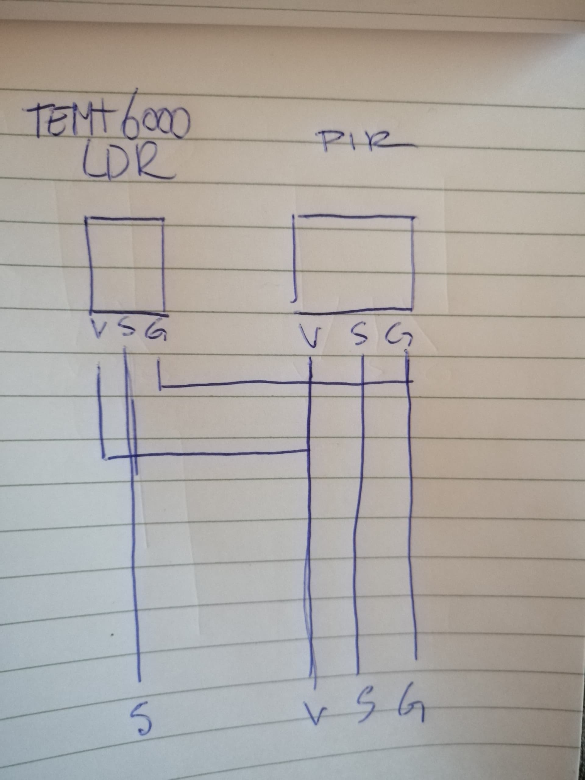
I have a LDR and a PIR that need to go into one enclosure and I have combined the VCC and GND to both of them into two cables (instead of four) to the arduino. The signals are not combined of course. Can or will this cause problems?
Hi
I have a LDR and a PIR that need to go into one enclosure and I have combined the VCC and GND to both of them into two cables (instead of four) to the arduino. The signals are not combined of course. Can or will this cause problems?
That should be OK depending on the length of the wires
Thanks Bob,
The wires will be about 3 meters from the sensors to the board. Is that going to be a problem?
It could well be, but that has nothing to do with the sensors sharing the same power connections
Have you tried it and does it work ?
Well, I've finished the sketch and printed the enclusure for both the Uno and the sensors. Before I had them in te sensorbox, they were connected with a few jumperwires and the values from the LDR seemed to be constant. The PIR also responded without any problems. So then I went on and used a 0.5 meter of wire (6 leads, that we also use to connect CNC controller boards) and I combined the LDR and PIR and suddenly the LDR had weird readings and the attached LED strips (for testing, only 10 LEDs each) stopped working when they were on full power. I thought it could be my laptop not having enough power on the USB port. Switched back to the desktop and had the same problem.
I removed the cable and replaced it with a CAT5 cable (copper) to see if that changes anything but it still gives me the same weirdness.
I wasn't sure the combining of the V and G might cause these problems.
The values I get now from the LDR, with constant (low) ambient lighting is:
0.00
2.00
1.00
2.00
1.00
4.00
3.00
2.00
1.00
1.00
1.00
1.00
3.00
2.00
1.00
0.00
0.00
1.00
1.00
2.00
6.00
4.00
2.00
2.00
0.00
1.00
1.00
3.00
4.00
4.00
1.00
0.00
1.00
0.00
0.00
But this should be - or was - more constant. The LEDS will only turn on when the LDR average of two measurements is lower than 2, so this is messing it all up ![]()
Hmmm OK, I've removed the wires and have jumper wires connecting it all again. The behaviour is still erratic to say the least so I uploaded the sketch that I tested the LDR with/ I have covered the LDR with black tape and shining upon it with a bright phone light, so the values should be ~0:
#define LIGHTSENSORPIN A0

void setup() {
  pinMode(LIGHTSENSORPIN,  INPUT);
  Serial.begin(9600);
}

void loop() {
  float reading = analogRead(LIGHTSENSORPIN);
  Serial.println(reading);
  delay(500);
}
Which it is:
23:55:52.931 -> 0.00
23:55:53.443 -> 0.00
23:55:53.958 -> 0.00
23:55:54.449 -> 1.00
23:55:54.959 -> 0.00
23:55:55.471 -> 0.00
23:55:55.948 -> 0.00
23:55:56.462 -> 0.00
23:55:56.988 -> 0.00
23:55:57.464 -> 0.00
23:55:57.970 -> 0.00
23:55:58.487 -> 0.00
23:55:59.000 -> 1.00
This exact same code I used in my 'bigger' sketch and I get this when the LEDstrips are NOT activated:
23:59:00.827 -> 0.00
23:59:00.862 -> 0.00
23:59:00.862 -> 0.00
23:59:00.862 -> 0.00
23:59:00.862 -> 0.00
23:59:00.862 -> 0.00
23:59:00.896 -> 0.00
23:59:00.896 -> 0.00
23:59:00.896 -> 0.00
23:59:00.896 -> 0.00
Which is good, because an average on that needs to be below a threshold of 2 to activate the LED strips. However, I still have the black tape around the sensor and the LED strips are inside a box with no light coming out, yet I get these readings from the LDR:
00:01:35.882 -> 0.00
00:01:35.916 -> 0.00
00:01:35.916 -> Beweging gezien!
00:01:35.916 -> Activeren verlichting!
00:01:36.560 -> 3.00
00:01:36.560 -> 5.00
00:01:36.594 -> 5.00
00:01:36.628 -> 3.00
00:01:36.628 -> 5.00
00:01:36.663 -> 6.00
So as soon as the PIR detects motion (Beweging gezien) and turns on the LEDs to max brightness, the values of the LDR bump up (and the threshold trigger is not activated, so it turns itself off).
I am confused since this all worked perfect until I tried to put it in a box. There has been no changes in code or the pinlayout, only longer cable to the terminals.
Is it possible that the pir signal is messing with the LDR signal?
Is the LDR under LED or fluorescent lighting that pulsates (invisibly) at mains frequency?
I've turned off all light near it and nothing changed. I did figure out what is was after taking it apart again. I had two small LED strips connected to it over the 5v pins on the board. Prior to attaching the longer cable to the sensors, I moved the V from the LEDs to the screw terminals at the front of the housing so it could actually close and there was the problem. After removing the strips from the terminals (which are also connected to the 5v pins) the LDR had normal readings again.
Still I don't really understand why moving the V from the board to the terminals would change anything but I have the strips (5 LEDs each) on a separate power supply now and it all works as before, so I'm happy it works again but still confused what happened there because that was my setup all the time, without any problems.
Just a quick question... is it possible to power the sensors from the main power supply (5v 20a) just like the LED strips and the board or should they be powered from the board? GND is coming from the same supply.
Thanks!
This topic was automatically closed 180 days after the last reply. New replies are no longer allowed.