So it should like this on board?:

Hi,
Not all at the same time, but use what you have on your protoboard, we are testing your wiring.
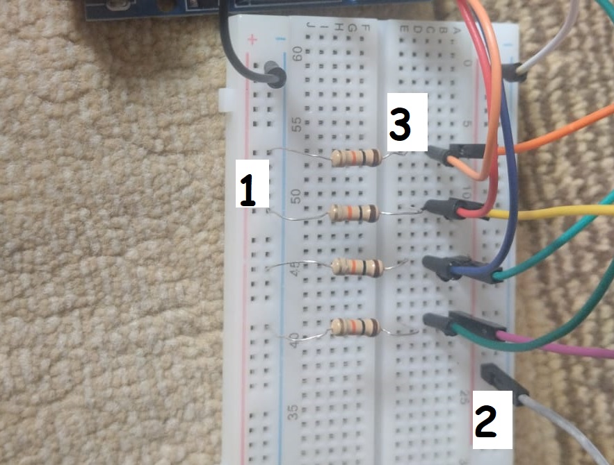
Point 1 is the gnd connection, point 2 is the 5V connection, point 3 is one of your analog input connections.
Jumper a wire from point 1 to point 3, you should get a serial reading of 0 for that analog input.
Then.
Remove the jumper and jump 2 to point 3, you should get 1023 as a serial reading for that analog input.
Tom.... 


So I did that and all 4 analogs (A0 to A3) showed 0 when connected to GND and 1023 when connected to 5V, they all seem to work fine

Could you please be more specific? This is my first project and english is my third language, so i'm struggling to understand what exactly you want me to connect point 1 to


Clever design there

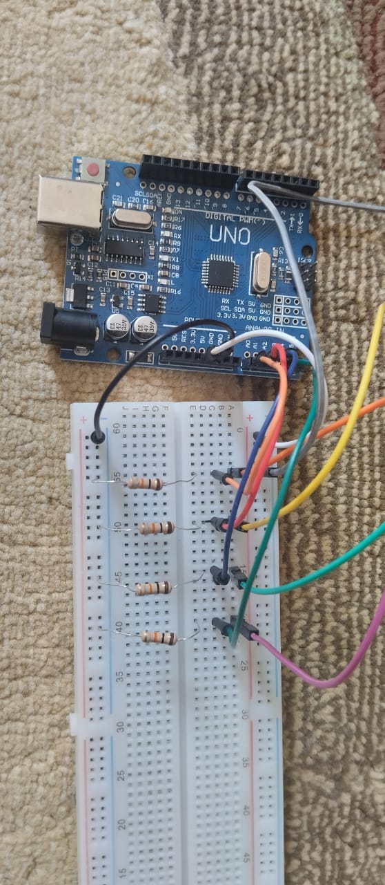
Here is my wire setup that (I believe) is the same as the one you sent. All wires coming from right are LDRs (grey/red is the positive for all LDRs)
I have this code to output LDR values, and they are still 0
void setup() {
  // initialize serial communication at 9600 bits per second:
  Serial.begin(9600);
}
void loop() {
  // reads the input on analog pin A0 (value between 0 and 1023)
  int analogValue0 = analogRead(A0);
  Serial.print("Analog reading0: ");
  Serial.println(analogValue0);   // the raw analog reading
  int analogValue1 = analogRead(A1);
  Serial.print("Analog reading1: ");
  Serial.println(analogValue1);   // the raw analog reading
  int analogValue2 = analogRead(A2);
  Serial.print("Analog reading2: ");
  Serial.println(analogValue2);   // the raw analog reading
  int analogValue3 = analogRead(A3);
  Serial.print("Analog reading3: ");
  Serial.println(analogValue3);   // the raw analog reading

  delay(500);
}
or this
Like I show in post #12
See the 4 LDR along the top?
One end is connected to 5V the other end to the resistor.
You can open the image and zoom in to see.
I don't work well with photos, but if you have one 5 V and four return it's ok. The pics of diagrams you posted would effectively connect all the legs of the LDRs together.
I have my wires setup just like in post#12 right now
Photo of it in post #31
I did that but AnalogRead(Ax) (x are numbers from 0 to 3) is 0 and sometimes spikes at 1-5
Have you tried tackling this problem by breaking it down into just one LDR? What readings do you get then?
Edit: I recommend having a DMM at hands when troubleshooting voltages and readings. Then you can quickly conclude if it's your LDR setup or the Arduino or the code that is the culprit.

I tried to do with just 1 LDR but readings were the same
I did that and all LDRs are 0 and A3 is 1023
What LDR do you have?