I'm doing a solar tracker based on Arduino, but my LDR analog read values are always either 0 or very close to 0 (max 10), no matter the level of light. I have checked the wiring, code but can't find the issue.
I copied configuration from here: https://www.instructables.com/Arduino-Solar-Tracker/
but without potentiometers (instead I made const dtime = 150 and tolerance = 20). My LDRs go like this: 5V -> LDR -> Ax (x number from 0 to 3) -> 10kOhm resistor -> GND. Just like in the link. Could you help identify where the issue might be?
First, make sure that you know how to use just one LDR (in a voltage divider) to make useful illumination measurements.
The resistor value is important and should be chosen to roughly match the LDR resistance in moderate levels of illumination.
This tutorial is a fine place to start.
His code is wrong.
The pin numbers are A0, A1, A2, A3. not 0,1,2,3
So I have tried doing the tutorial and then started gradually adding more and more LDRs. I found that the more LDRs I had connected, the lower their readings became. For the same lighting level with 1 LDR it was around 500, with 2 around 300, with 3 around 110, and finally with 4 all readings became 0. It does not matter to which GND the wires are connected to. However now even after disconnecting 3 LDRs (so I have 1 connected right now) the readings are still showing 0. How can I solve this problem?
See post #3
I immeditely changed the analogreads from 0,1,2,3 to A0, A1, A2, A3 when adapting the code. The problem was still present
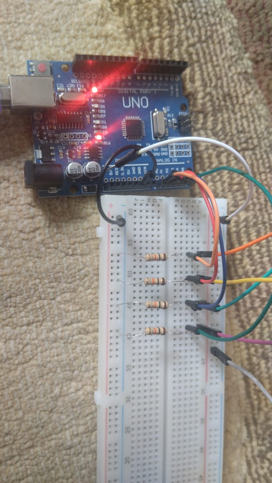
- You could show us good images of your actual wiring.

I removed all wires to test LDRs one by one. I made wiring the same as in the link in post #1 but without the potentiometer (and all wires connected to it).
You can't power servos from the Uno 5V out, they draw too much current.
Disconnect the servos and put come print statements in the code and see if the LDRs work
Can Uno power 4 LDRs at the same time?
Yes (unless you connect them incorrectly).
If connected correctly, they should need no more than about half a milliamp each.


Here is my wiring image. The gray wire is connected pin of all LDRs. It still outputs zeroes. Code I used to output is below:
void setup() {
  // initialize serial communication at 9600 bits per second:
  Serial.begin(9600);
}
void loop() {
  // reads the input on analog pin A0 (value between 0 and 1023)
  int analogValue0 = analogRead(A0);
  Serial.print("Analog reading0: ");
  Serial.println(analogValue0);   // the raw analog reading
  int analogValue1 = analogRead(A1);
  Serial.print("Analog reading1: ");
  Serial.println(analogValue1);   // the raw analog reading
  int analogValue2 = analogRead(A2);
  Serial.print("Analog reading2: ");
  Serial.println(analogValue2);   // the raw analog reading
  int analogValue3 = analogRead(A3);
  Serial.print("Analog reading3: ");
  Serial.println(analogValue3);   // the raw analog reading

  delay(500);
}
When you analogRead() and pass 0, it is interpreted as A0. Same with 1, 2 and 3.
I know instructables can be bad, but it would surprise me if they were so very bad that the published code had zero chance of being correct.
a7
No, the Arduino IDE also accepts channel number for analog inputs.
Where are the LDRs? Please post an photo of the entire circuit.


Hi, @kover9
Welcome to the forum.
Do you have a DMM? (Digital MultiMeter)
Measure the voltage at A0, A1, A2 and A3 with respect to the the gnd.
Also check that you have 5V at the grey wire on the protoboard and at the red wire behind the LDRs in your sensor assembly.
Tom.... 


Hello TomGeorge, I don't have a DMM but I had some relative to check the board and LDRs and he said they worked. The red and grey wires are connected together as an extension, I didn't have any red wires left so I had to use the grey one
That's fine, you need to get an inexpensive DMM to help you, it is an invaluable tool.
Try this;
Connect A0 to 5v and then to gnd, note the readings on the serial output.
Do this with a jumper from A0 to 5V and gnd ON THE UNO.
Then;
Do it to the protoboard end of your wiring, that is the A0 wire to the 5V wire then A0 wire to gnd, all on the protoboard.
This will check the basic continuity between UNO and the board.
Hope that makes sense.
Tom....