LED Indicator with Arduino Rotary Selector Switch

Hello!

I feel like I'm missing something here and cannot seem to figure out where I'm going wrong. I have a Mini 8-Way Rotary Selector Switch connected to my Pro Micro and as a proof of concept have confirmed that it is working as expected. I am running QMK and plan on using the switch for layer selection, but for now, it's just outputting numbers so I can validate that it's working. My code looks as follows:

/* define DIP switch pins for rotary switch */
#define DIP_SWITCH_PINS { B3, B2, B6, D7, E6 }

and later for handling:

bool dip_switch_update_user(uint8_t index, bool active) {
    switch (index) {
        case 0: {
            if (active) {
                tap_code16(KC_1);
            } else {
                
            }
      break;
        }
    case 1: {
            if (active) {
                tap_code16(KC_2);
            } else {
                
            }
      break;
        }
    case 2: {
            if (active) {
                tap_code16(KC_3);
            } else {
                
            }
      break;
        }
    case 3: {
            if (active) {
                tap_code16(KC_4);
            } else {
                
            }
      break;
        }
    case 4: {
            if (active) {
                tap_code16(KC_5);
            } else {
                
            }
      break;
        }
  }
    return true;
}

The issue I'm running into is that I'm trying to save as many pins as possible (the board is already a 5x4 switch matrix with the SP8T), while also trying to add LED indicators to the 8-way to show which layer is active. I do know that I can run each LED to pin and set high state as needed, but that requires more pins than I have available. I've tried connecting the LEDs as follows:

This works, but the LED remains on until you're on the selection, which turns it off. Is there any way to reverse this? So the LED is only on when the switch is active?
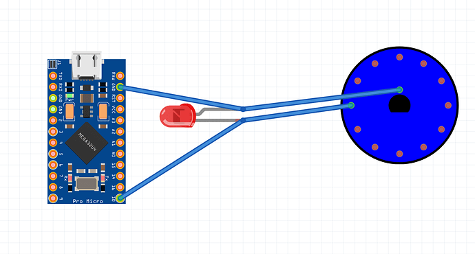
Please post the entire code. That snippet makes no sense.
A little schematics would be nice as I'm not familiar with the pins on that controller.

Sure! I just didn't want to end up clogging the post with a bunch of code.

As for the standard config, the config.h is as follows:

#pragma once

#include "config_common.h"

/* USB Device descriptor parameter */
#define VENDOR_ID       0xFEED
#define PRODUCT_ID      0x6060
#define DEVICE_VER      0x0001
#define MANUFACTURER    Daniel
#define PRODUCT         20boy

/* key matrix size */
#define MATRIX_ROWS 5
#define MATRIX_COLS 4

/* key matrix pins */
#define MATRIX_ROW_PINS { F4, F5, F6, F7, B1 }
#define MATRIX_COL_PINS { D1, D0, D4, C6 }			 /* Note this should be changed at some point so we're not using serial pins */
#define UNUSED_PINS

/* COL2ROW or ROW2COL */
#define DIODE_DIRECTION COL2ROW

/* define DIP switch pins for rotary switch */
#define DIP_SWITCH_PINS { B3, B2, B6, D7, E6 }

/* Set 0 if debouncing isn't needed */
#define DEBOUNCE 5

as for the actual keymap.c which defines the dip, it's as follows:

#include QMK_KEYBOARD_H


enum layer_number {
  _0 = 0,
  _1,
  _2,
  _3,
  _4,
};

const uint16_t PROGMEM keymaps[][MATRIX_ROWS][MATRIX_COLS] = {
	[_0] = LAYOUT( 
		KC_GRV, 	KC_VOLD, 	KC_VOLU, 	KC_BSPC,
		KC_P7, 		KC_P8, 		KC_P9, 		KC_PAST,
		KC_P4, 		KC_P5, 		KC_P6, 		KC_PSLS,
		KC_P1, 		KC_P2, 		KC_P3, 		KC_PPLS,
					KC_P0,  	KC_PDOT,    KC_PENT
		),
  [_1] = LAYOUT( 
    KC_GRV,   KC_VOLD,  KC_VOLU,  KC_BSPC,
    KC_P7,    KC_P8,    KC_P9,    KC_PAST,
    KC_P4,    KC_P5,    KC_P6,    KC_PSLS,
    KC_P1,    KC_P2,    KC_P3,    KC_PPLS,
          KC_P0,    KC_PDOT,    KC_PENT
    ),
  [_2] = LAYOUT( 
    KC_GRV,   KC_VOLD,  KC_VOLU,  KC_BSPC,
    KC_P7,    KC_P8,    KC_P9,    KC_PAST,
    KC_P4,    KC_P5,    KC_P6,    KC_PSLS,
    KC_P1,    KC_P2,    KC_P3,    KC_PPLS,
          KC_P0,    KC_PDOT,    KC_PENT
    ),
  [_3] = LAYOUT( 
    KC_GRV,   KC_VOLD,  KC_VOLU,  KC_BSPC,
    KC_P7,    KC_P8,    KC_P9,    KC_PAST,
    KC_P4,    KC_P5,    KC_P6,    KC_PSLS,
    KC_P1,    KC_P2,    KC_P3,    KC_PPLS,
          KC_P0,    KC_PDOT,    KC_PENT
    ),
  [_4] = LAYOUT( 
    KC_GRV,   KC_VOLD,  KC_VOLU,  KC_BSPC,
    KC_P7,    KC_P8,    KC_P9,    KC_PAST,
    KC_P4,    KC_P5,    KC_P6,    KC_PSLS,
    KC_P1,    KC_P2,    KC_P3,    KC_PPLS,
          KC_P0,    KC_PDOT,    KC_PENT
    ),


};

bool dip_switch_update_user(uint8_t index, bool active) {
    switch (index) {
        case 0: {
            if (active) {
                tap_code16(KC_1);
            } else {
                
            }
      break;
        }
    case 1: {
            if (active) {
                tap_code16(KC_2);
            } else {
                
            }
      break;
        }
    case 2: {
            if (active) {
                tap_code16(KC_3);
            } else {
                
            }
      break;
        }
    case 3: {
            if (active) {
                tap_code16(KC_4);
            } else {
                
            }
      break;
        }
    case 4: {
            if (active) {
                tap_code16(KC_5);
            } else {
                
            }
      break;
        }
  }
    return true;
}

Again, this is a QMK firmware. And while different from a normal setup, the electronics should still be the same!

Let me know if you have any other questions.

What is the "code" You posted? I see no setup(), no loop(), no call to the function dip_switch_update_user.

Are You being funny in some way?

Not being funny at all.

Check out QMK here. It's a keyboard firmware based off of ChibiOS. While it does look a little unorthodox, I can promise you that this is functioning code :slight_smile:

Thanks for the opportunity but that's way too much to dig into.
I have to drop any code checking.

Regarding the LEDs. The wiper is connected to GND. Fine. Connect all LED anodes to positive and their cathodes to the rotating switch. By the way, there ought to be a current limit resistor in serie with the LEDs. Add it between the common anodes and the positive. Make sense?

Regarding the LEDs. The wiper is connected to GND. Fine. Connect all LED anodes to positive and their cathodes to the rotating switch. By the way, there ought to be a current limit resistor in serie with the LEDs. Add it between the common anodes and the positive. Make sense?

I should have been a bit more clear, but the LEDs actually have the resistors presoldered on the wires!

If I'm understanding your comment correctly, that's how it's currently set up. LED anode is connected to the pinout (+), and their cathodes connecting to the wiper going to ground (-). Am I misunderstanding that? I do apologize, as when it comes to circuitry I'm a little green.

The cathode of the LED should not be connected to the wiper! Connect them to their respective radial pin on the switch.

I think I had my cathode/anode's backwards there :stuck_out_tongue:

So to accomplish this, would I connect the anodes(-) to something like the VCC pin for power, and the cathodes(+) directly on the switch pin? Again, sorry for all the questions - I really do appreciate you taking the time to work this out with me

Ooops. You have got the facts reversed. Anode is where the current enters the LED and cathode where the current leave, goes to GND.

Thanks for replying this quickly. That makes it easier to reply as not 20 other member questions are circulating in the head.

You are an absolute SAINT!

This accomplished exactly what I wanted. Thank you so so much!

This topic was automatically closed 180 days after the last reply. New replies are no longer allowed.