Hi, I am using an Arduino Uno. I tried to turn on the led when I pressed the button.
In my code, the button and the alarm were working fine, but the led is not turning on.
when I tried to turn on the led itself without the button and the alarm, it was working fine. So, I do not think led itself is a problem.
Can you help me find out why the led is not on? I attached my Arduino and the code below for the reference.
Thanks!
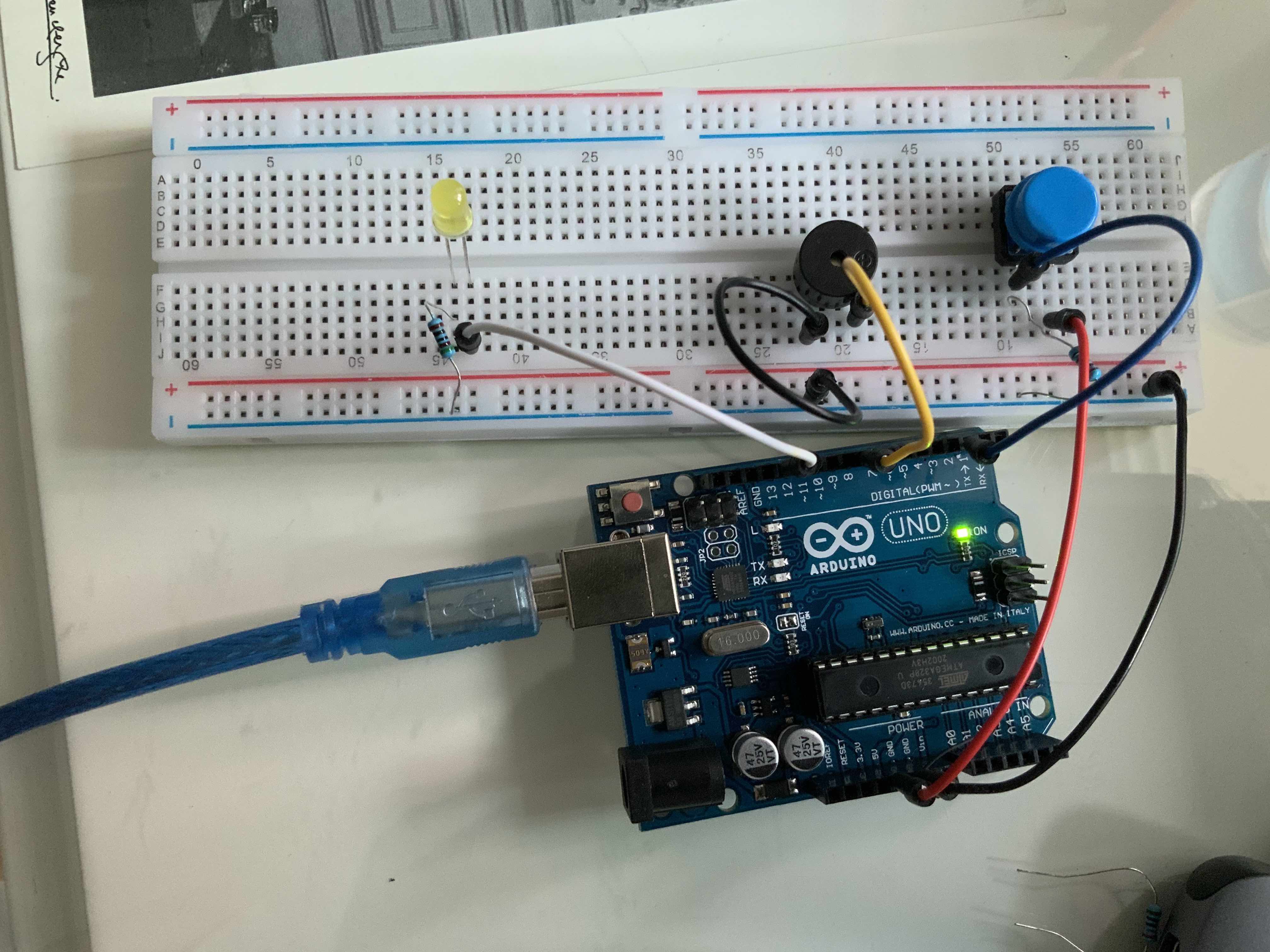
Photos of the hardware don't give a reliable indication of connections. Please make a simple pencil drawing showing the connections and post a photo of the drawing.
I'm not familiar with the SimpleTimer library. I do all my timing with millis() as illustrated in Several Things at a Time.
yejincolor:
Thanks for the reply, but the button is working fine with my original code. My problem is the led light that is not turning on.
What does the serial debug output tell you?
i.e. is...
a) the code doing the right thing, but the led just not illuminating
b) the debug output is also doing the wrong thing, so the led is consistent with what the code says it is doing (just not illuminating as you want it)
You seem to have a pull-down Resistor on your button? That is good, but It looks to me that the button is also connecting to ground when pressed? I could be wrong. This is why we need a circuit diagram.
Personally I would scrap the external resistor and use the internal pull-up. It is much easier and eliminates an external component.
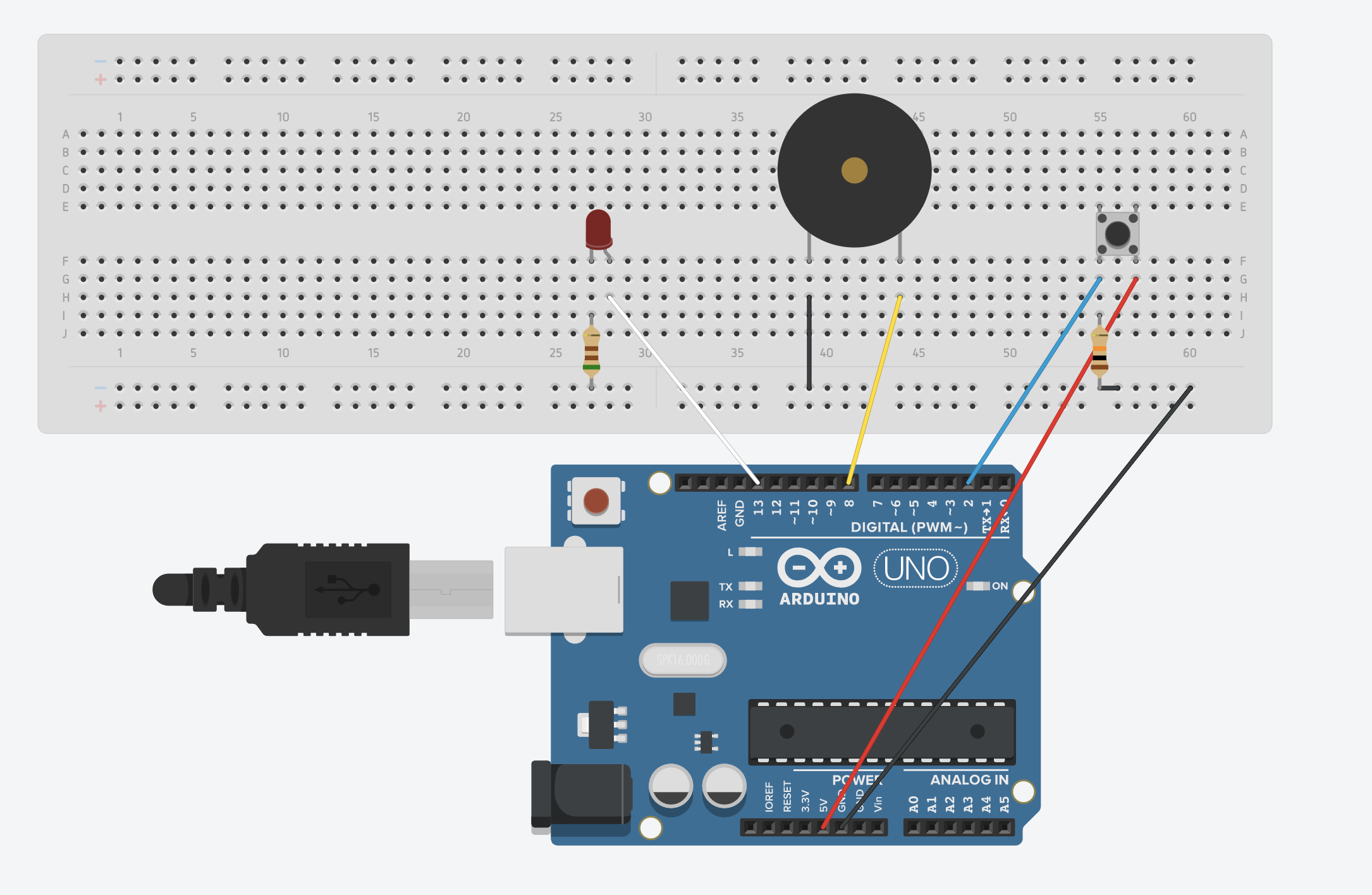
This not your real circuit. It is just a fritzing image. So it might be that there are still differencies between your real breadboard and the image.
Usually on these long breadboards the contactlines that run along the long outsides (horizontal in your picture) are divided in the middle. This means your connection to ground of the arduino (the black wire) ends in the middle.
The connection towards the LED trough the resistor has no connection to ground. That might be the reason why the LED does not light up.
In the fritzing diagram a 150 Ohm-resistor is used
For 5V this value is a bit low. The current will be (5V -1.8V) / 150 Ohm = 21 mA.
Arduino-IO-pins are rated for 20 mA. The LED will surely light up with 5 mA. Of course not with maximum brightness. But you will clearly see it.
5mA requieres a resistor of (5V -1.8V) / 0.005A = 640 Ohms.
From the real picture I cannot see the colors of the rings on the resistors. Do you have a digital multimeter
with which you can measure resistors?
If not: If you want to do more than serial-output to your computers screen = add some hardware a digital multimeter is a must. You will encounter dozens of situations where you have to check electrical things with a digital multimeter.
best regards Stefan
We need to establish if it is the button that isn't working or the LED.
Edit: Stefan has a very good point about the break in the breadboard "busbar" lines.
This is as indicated by the break in the blue and red lines in the picture (post #3).
From the real picture I cannot see the colors of the rings on the resistors. Do you have a digital multimeter
with which you can measure resistors?
If not: If you want to do more than serial-output to your computers screen = add some hardware a digital multimeter is a must. You will encounter dozens of situations where you have to check electrical things with a digital multimeter.
I would recommend this one:
price $25. Of course there are cheaper ones but his one offers measuring of frequency, dutycycle, diodes and capacity
If the shipping-costs are not too high I would recommend this one
This has even a build in flashlight and bluetooth. So you can display the measurings on your smartphone. And you can use it as a slow-speed oscilloscope or long-term-datalogger.
yejincolor:
Thank you StefanL38 and pcbbc! My problem was solved!
I did not know the + and - horizontal line on my breadboard was divided into two!
Yes, I'm fairly the manufacturers started doing this a while back. I'm also fairly sure I never had this issue at school, but that was about 35 years ago...
I'm sure it's useful if you require different rails for different parts of your circuit.
But it's caught a few people out over the years, so no shame in it. Usually people just wire in jumpers to "bridge the gap". I've also seem people remove the back of the breadboard and permanently solder across to to bars. Would recommend removing the break in the lines with a Sharpie if doing that though, so you don't forget.
Edit: Again Stefan has excellent advice with regards to a meter.
Also it is worth pointing out that a meter cannot measure the difference between 0v and a floating pin. So if you want to test if a pin is 0v (and not floating) the way to do that is test from 5v to the pin. If the pin is indeed 0v you will see +/-5v on the meter, otherwise you will still see 0v if it is floating.