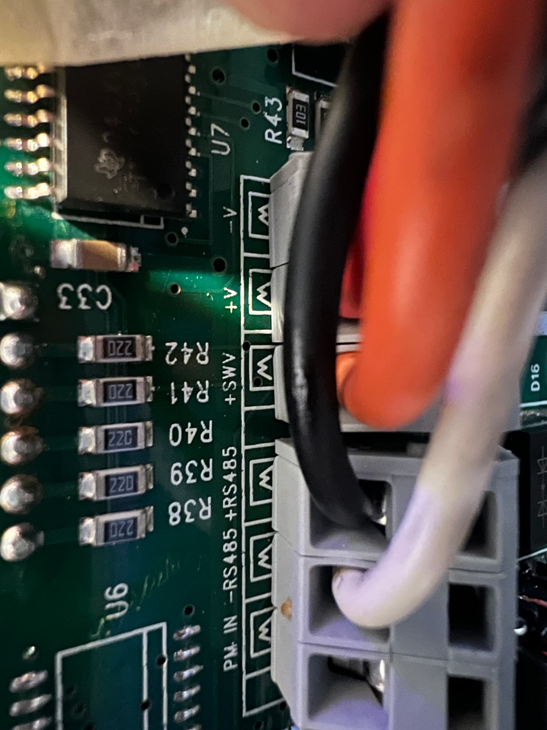
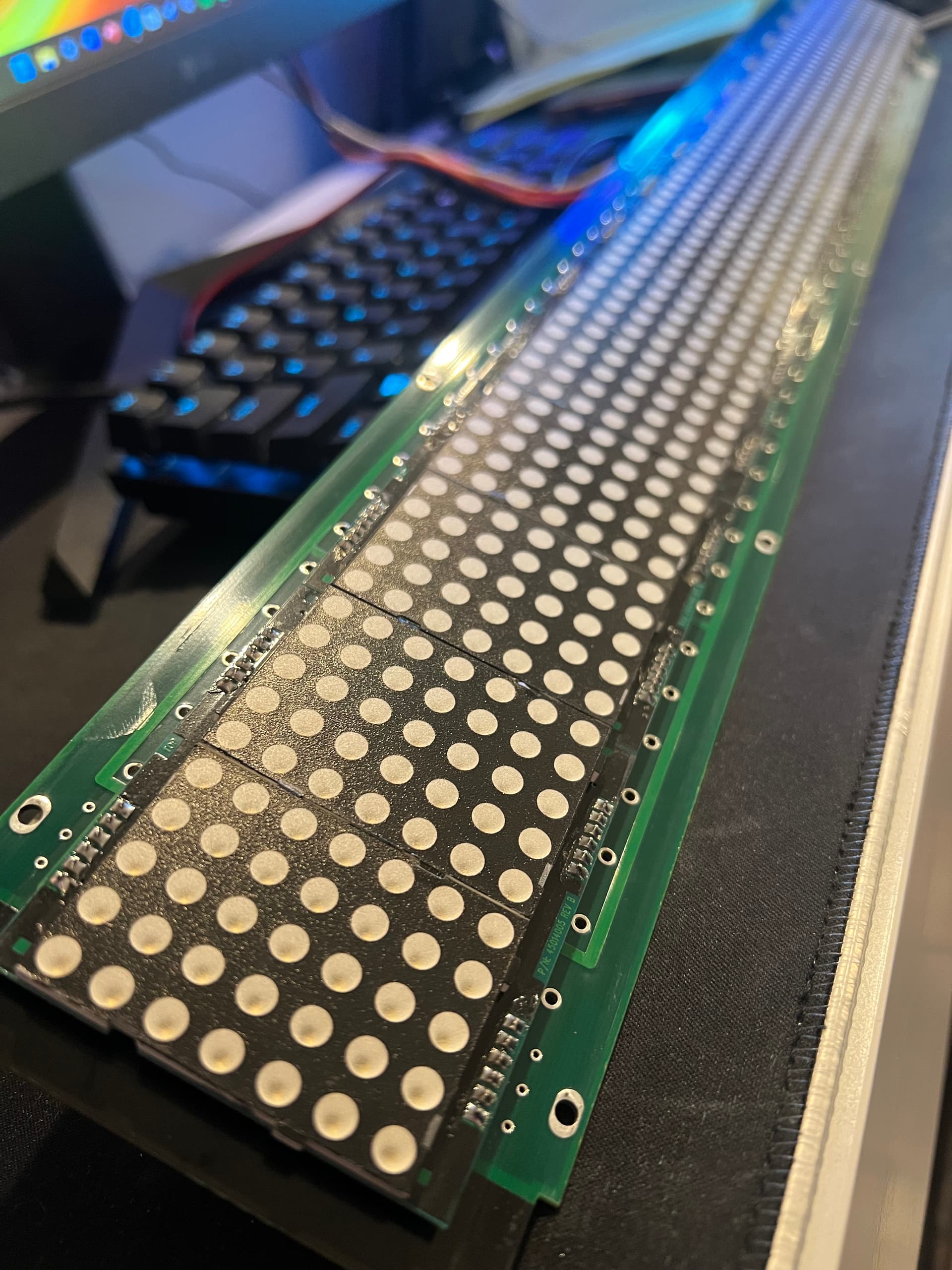
I have a board that i want to use in a digital clock. its 15 @ 7x5 matrix boards connected together for a scrolling display. Im hoping to use a nano or pro micro board to run it but I dont know how this pinout is meant to connect to the board.
You would connect this to the Rx & Tx pins of an unused UART on the Arduino. For this reason I would recommend using the Pro Micro, which has an unused UART, unlike Nano (assuming you mean Nano V3).
Your next question will be what code to use. Here, I can't help, since your picture gives no clues about that.
Thank you so much for helping me with this. I have a pro micro to use so the nano goes for something else.
I’ll source one of these and I’ll take a picture of the scrolling display and add soon.
Yes. Look RS485 up on Wikipedia or something to learn about it.
But an RS485 adapter is only one piece of the jigsaw you will need to solve in order to control this display with Arduino. So don't buy the adapter yet. See if you can find answers to some of the other problems first, so you don't waste your money and get your hopes up too high.
What you will need to do is to identify this board, it's manufacturer and model number, and try to find a manual that explains how to use it. A description of what protocols it uses, and, ideally, some example code, even if it is not Arduino code, would be great to have in this manual.
Without this documentation, your chances of success are very low. Pretty much zero, in reality.
So good luck in your searching. Use this topic to share links to what you find and the forum may be able to provide further help.
A much simpler approach would be to buy some matrix displays on Amazon/eBay/etc based on the max7219 chip. There are lots of example Arduino code and libraries available for these displays.
If this were my problem I'd hook up the RS485 module (after learning a bit about how RS485 works) and use it to throw some data at the display and see if anything appeared on the display. If something did appear then I'd try to work out the relationship between the data I sent and the LEDs that lit. I'd do so with the expectation that I'd fail and I'd probably end up throwing the thing away, but always with the hope of learning something interesting. Nothing ventured, nothing gained.
Apart from that: what @PaulRB said, every word of it.
Have you already looked at the IC's hiding under that tape?
Maybe it helps to identify those to see how the LED matrices are driven?
If I couldn't find any supporting software to drive the board, I would find out what MCU is connected to that RS485 port and then see how that MCU drives the LEDs.
The wires in the previous pictures were able to be used as power, ground and accessory which I’ve hooked directly to the power as well. The 2 other wires which are labelled +RS485 and -RS485 will be connected to an RS485 module and I’m hopeful once it’s coded with either a pro micro or a nano.
@PaulRB I’m still searching for any paperwork or diagrams on this display, I know this display like in the picture comes up with a generic clock that’s waiting for communication once it’s powered. It even keeps time accurately, and it it’s previous application once the right time was sent it would update accordingly.