ledcWriteTone conflicts with Interrupts

With interrupts declared, when calling ledcWriteTone() to activate a buzzer, some internal conflict arises that causes the interrupt to be triggered continuously.

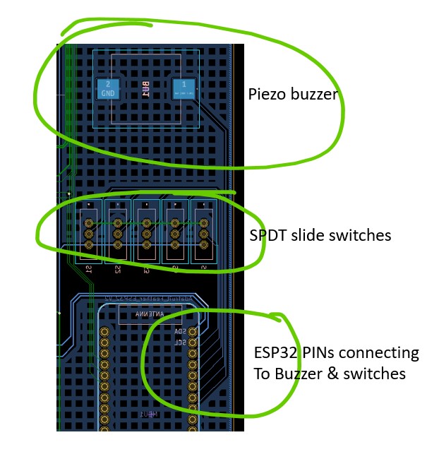
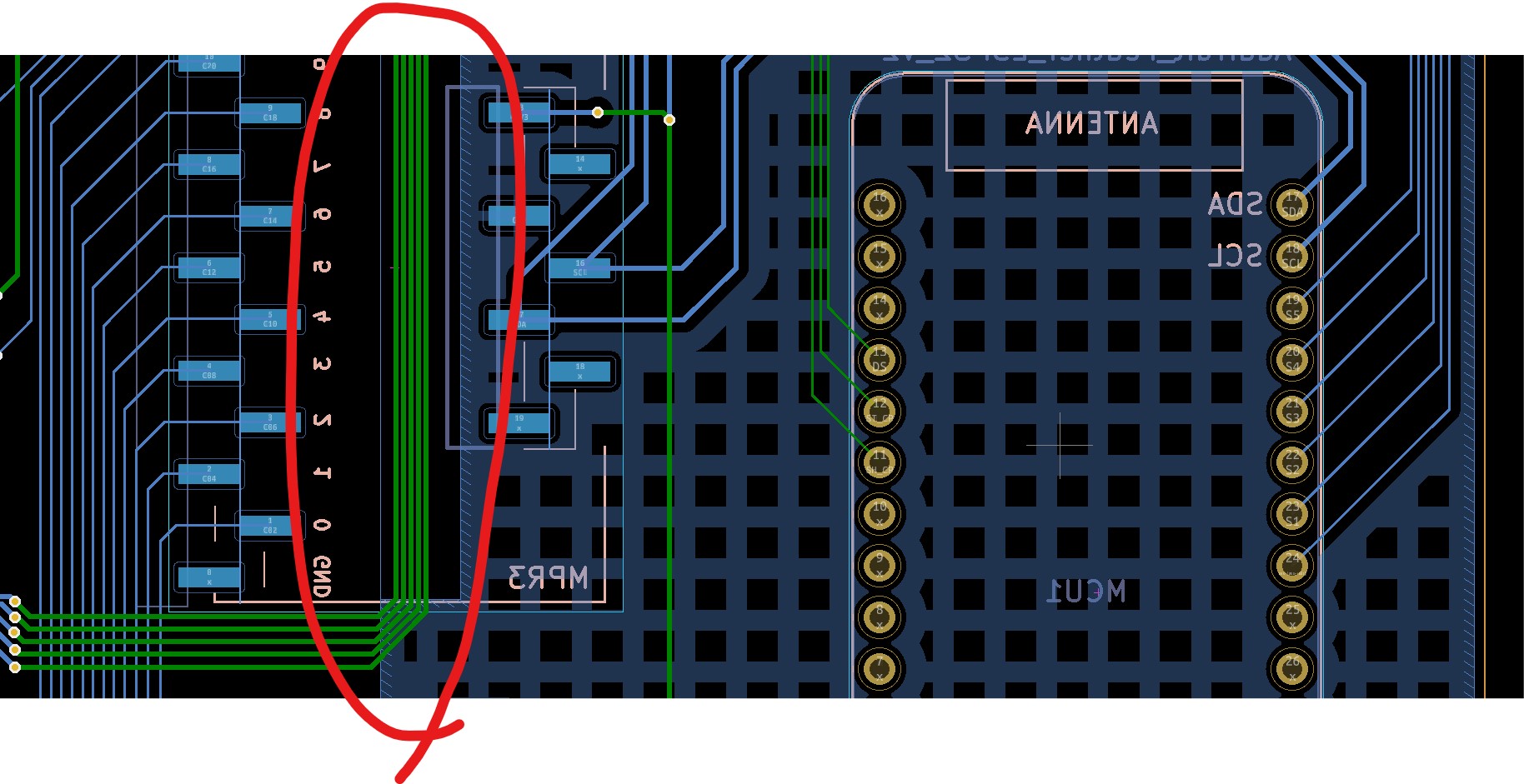
I have 5 SPDT physical switches (to function as DIP switches) connected to 5 pins in an ESP32. If all pins are HIGH, all is good. One pin (any pin) can change to LOW and all is good (including the "click" sound generated by the buzzer). But once a second pin changes to LOW, its ISR is triggered continuously. When disabling the call to ledcWriteTone(), any combination of pins cans change and all is good.

I tried several tones, durations and channels for the buzzer's ledcAttachPin() (the ESP32 has 16 channels for this function) and even tried declaring the ISR without the "IRAM_ATTR" qualifier (to force it into flash vs RAM). No luck.

I'm using the Arduino-ESP32 core ver 2.0.4. I found some references of conflict between PWM (especially w/stepper motors) and interrupts but all for older versions of the core (pre 2.0).

The (awesome) sequence to create the 5 ISR's using parameters was provided by @killzone_kid here: (Are you basically looking to pass an argument to the interrupt routine?)

Any leads, thoughts or previous experiences?
Thanks!

//---declarations for interrupts
typedef struct {
  const uint8_t PIN;
  bool changed;
  bool value;
} fSwitch;

// SPDT switches connected to pins 27,33,15,32,14 (all adjacent in the Adafruit ESP32 Feather V2)
fSwitch FS[5] = {{27,0,0},{33,0,0},{15,0,0},{32,0,0},{14,0,0}};

volatile bool sFlag = false;
void IRAM_ATTR chkFS(void *arg) {
  fSwitch *fs = static_cast<fSwitch *>(arg);
  fs->changed = true; 
  fs->value = digitalRead(fs->PIN); 
  sFlag = true;
}

//---declarations for Buzzer
int buzzPin = 12;
int buzzChan = 0;
long buzzTimer = 0;

void setup() {
  Serial.begin(115200);
  Serial.println("Start");
  for (byte i=0; i<5; i++) {
    pinMode(FS[i].PIN,INPUT); 
    FS[i].value = digitalRead(FS[i].PIN); // initial state of each switch
    Serial.println("Initial State FS" + String(i) + "=" + String(FS[i].value)); 
    attachInterruptArg(FS[i].PIN,chkFS,&FS[i],CHANGE);
  } 
  ledcAttachPin(buzzPin, buzzChan);
}

void loop() {
  if (sFlag) {  // if any PIN has changed  
    ledcWriteTone(buzzChan,300); 
    buzzTimer = millis(); 
    sFlag = false;
    for (byte i=0; i<5; i++)
      if (FS[i].changed) { // determine which PIN changed
        Serial.println("Changed State FS" + String(i) + "=" + String(FS[i].value)); 
        FS[i].changed = false;
      }
  }
  if (millis() - buzzTimer > 40) ledcWriteTone(buzzChan,0); 
}

Just FYI: all the pins used for the switches (27,33,15,32,14) and for the buzzer (12) are GPIO pins (see pinout, below).

And BTW: if instead of using interrupts, I simply cycle in the main loop() checking for changes in the pins, all is good. This eliminates any electrical issue and centers the problem in the simultaneous use of ledcWriteTone & Interrupts.

//---declarations for switches
const byte pinFS[] = {27,33,15,32,14};
bool statFS[5];

bool readFS(byte pin) {
  bool done = false;
  bool act = false;
  bool prev = digitalRead(pin);
  byte d = 1;
  while (!done) {
    act = digitalRead(pin);  
    if (act == prev) d++; else d=1;
    prev = act;
    if (d > 8) done = true; // 8 = debounce number of identical samples
  }
  return act;
} 

//---declarations for Buzzer
int buzzPin = 12;
int buzzChan = 0;
long buzzTimer = 0;

void setup() {
  Serial.begin(115200);
  Serial.println("Start");
  for (byte i=0;i<5;i++) {
    pinMode(pinFS[i],INPUT);  
    statFS[i] = readFS(pinFS[i]);
    Serial.println("initial status " + String(i) + "=" + String(statFS[i]));
  }
  ledcAttachPin(buzzPin, buzzChan);
}

void loop() {
  for (byte i=0;i<5;i++) { //chk all pins
    bool temp = readFS(pinFS[i]);
    if (statFS[i] != temp) {
      statFS[i] = temp;    
      ledcWriteTone(buzzChan,300); 
      buzzTimer = millis(); 
      Serial.print("Changed " + String(i) + " to "); Serial.println(statFS[i]);
    }
  } 
  if (millis() - buzzTimer > 80) ledcWriteTone(buzzChan,0); 
}

Its probably switch contact bounce causing the issue.

Your polling method works because you've added software debounce and removed interrupts.

Testing on Wokwi using an ESP32-S2, I've used 5 dip switches (these have no contact bounce added) on GPIO33-37 and used INPUT_PULLUP. Other than this, your interrupt code example is untouched.
Simulation

You may need to add hardware debounce (capacitor) to your SPDT switches to avoid multiple interrupts during any switch contact transition.

Thanks @dlloyd !

When using the interrupt method without ledcWriteTone (i.e. not generating any sound), even when there is some switch contact bounce, eventually the system state is stable (after two or three bounces, if at all), that is, interrupts are no longer called.

But when invoking ledcWriteTone, the instability appears, that is, the ISR is called non-stop and the Serial.println statement reports the same state (i.e. LOW), no bouncing.

The SPDT switches' central terminal is connected to an ESP32 pin. The two outside terminals are connected to GND and VCC respectively. I ran a modified version of your simulation using slide switches and it even simulated the bounce, but it also reached stable state (after a few bounces). I could not find in wokwi's DOCs what version of the Arduino-ESP32 core it's using (to replicate in my computer) but I'm assuming it's using the latest version.

This is why I suspect that ledcWriteTone is somehow inserting the instability?

SOLVED ish... not the why, but at least the what & the how

So it wasn't hardware bouncing (it seems). The ledcWriteTone() statement triggers the ISR of PINs in LOW only when allowed to produce sound (i.e. > 0 ms). Sort of like a software bounce? (is that a thing?)

The statement itself does not trigger the ISR: if the ledcWriteTone(Channel,0) command is issued w/o delay, the system remains stable.

The code shared below prints the changed PINs before the ledcWriteTone(channel, freq) statement and after ledcWriteTone(Channel,0) statement (i.e. once the sound delay() is finished). The Serial output shows the behavior mentioned (created by physically sliding to LOW each switch in order).

In any case some simple debounce routine will be beneficial just to cover all bases (i.e. 5 or 6 consecutive identical digitalRead()'s of the triggered PIN or using something like xTaskGetTickCount();)

14:26:17.086 -> Start
14:26:17.086 -> Initial State FS0=1
14:26:17.086 -> Initial State FS1=1
14:26:17.086 -> Initial State FS2=1
14:26:17.086 -> Initial State FS3=1
14:26:17.086 -> Initial State FS4=1
14:26:18.915 -> 
14:26:18.915 -> Early Change FS0=0
14:26:20.042 -> 
14:26:20.042 -> Early Change FS1=0
14:26:20.089 -> Late Change FS1=0
14:26:21.168 -> 
14:26:21.168 -> Early Change FS2=0
14:26:21.215 -> Late Change FS0=0
14:26:21.215 -> Late Change FS1=0
14:26:21.215 -> Late Change FS2=0
14:26:22.287 -> 
14:26:22.287 -> Early Change FS3=0
14:26:22.334 -> Late Change FS0=0
14:26:22.334 -> Late Change FS1=0
14:26:22.334 -> Late Change FS2=0
14:26:22.334 -> Late Change FS3=0
14:26:29.566 -> 
14:26:29.566 -> Early Change FS4=0
14:26:29.614 -> Late Change FS1=0
14:26:29.614 -> Late Change FS2=0
14:26:29.614 -> Late Change FS3=0
14:26:29.614 -> Late Change FS4=0

Code:

//---declarations for interrupts
typedef struct {
  const uint8_t PIN;
  bool changed;
  bool value;
} fSwitch;

fSwitch FS[5] = {{27,0,0},{33,0,0},{15,0,0},{32,0,0},{14,0,0}};
volatile bool sFlag = false;

void IRAM_ATTR chkFS(void *arg) {
  fSwitch *fs = static_cast<fSwitch *>(arg);
  fs->value = digitalRead(fs->PIN);
  fs->changed = true; 
  sFlag = true;
}

//---declarations for Buzzer
int buzzPin = 12;
int buzzChan = 0;
long buzzTimer = 0;

void setup() {
  Serial.begin(115200);
  Serial.println("Start");
  for (byte i=0; i<5; i++) {
    pinMode(FS[i].PIN,INPUT); 
    FS[i].value = digitalRead(FS[i].PIN); //---initial state of each switch
    Serial.println("Initial State FS" + String(i) + "=" + String(FS[i].value)); 
    attachInterruptArg(FS[i].PIN,chkFS,&FS[i],CHANGE);
  } 
  ledcAttachPin(buzzPin, buzzChan);
}

void loop() {
  if (sFlag) {  
    for (byte i=0; i<5; i++) //---list PINs changed by slide switch action
      if (FS[i].changed) { 
        Serial.println("\nEarly Change FS" + String(i) + "=" + String(FS[i].value)); 
        FS[i].changed = false;
      }
    ledcWriteTone(buzzChan,300); 
    delay(30); //---PINs changed by ledcWriteTone occur during sound emission in delay()
               //---therefore no delay or delay=0 produce no misbehaving
               //---any delay duration (> 0) is immaterial as long as end of ledcWriteTone
               //---occurs within the sFlag loop.
    ledcWriteTone(buzzChan,0); 
    //buzzTimer = millis(); 
    sFlag = false;
    for (byte i=0; i<5; i++) //---list PINs changed by ledcWriteTone
      if (FS[i].changed) { 
        Serial.println("Late Change FS" + String(i) + "=" + String(FS[i].value)); 
        FS[i].changed = false;
      }
  }
  //if (millis() - buzzTimer > 30) ledcWriteTone(buzzChan,0);  
  //----if time for Buzz sound ending is determined outside of sFlag loop,
  //----subsecuent iterations of the sFlag loop trigger aditional calls to the 
  //----ISRs of the PINs in LOW state, becomimg recursive
}

Crosstalk or ground bounce perhaps.

GROUND BOUNCE!

I didn't even know it existed. After some deep Google-diving, it certainly looks as the missing Why: only PINs that are currently LOW are affected and the ground bounce probably happens in a clock cycle so the next immediate action after the "bounce" interrupt is another interrupt showing it LOW (therefore un-interceptable in software).

(for those who just joined us, the What & How can be found in post #5)

Below is a partial screenshot of my PCB, where the Buzzer PIN (BTW: surrounded by the meshed GND fill), travels right next to the Switch PINs into the ESP32. I made these traces 0.127mm wide (5 mils), without really knowing why (disclaimer: it's my first PCB...), but all this, tied to the voodoo that is PCB electric design = clearly a source for ground bounce. More decoupling capacitors next time!

Thanks @gfvalvo for leading me into something new! (and the Why). And also thanks to @dlloyd for pointing me to wowki, something (awesome) I did not know existed (plus you were on the right track too).

Love this forum!

I would have titled it "Crosstalk". Those traces are insanely close together. Did you run a DRC?

Yep. All checks & balances passed with flying colors (KiCad 6 and JLCPCB's tolerances). My rule of thumb was to space them 2x the trace width (for signal traces). Power traces (like those for LEDs) are closer (highlighted in red below) and have presented no issues (yet.... :sweat_smile:)

Your wifi antenna is placed over a ground plane. It will badly detune the antenna and impair the wifi performance.

Good point. As dumb luck would have it (this time), the ESP32 dev board is placed over headers, creating a 2mm air gap that saved the day. Thanks!!

2mm is not enough. Sorry. That is still in the near field of the antenna. I'm not saying it won't work. I'm saying it will greatly impact the range.

The first simulation uses "clean" switching (no bounce) ... only one interrupt occurs per press.

This simulation uses pushbuttons that (by default) have about 2ms of nasty bounce (on-press and on-release). I've turned off this bounce for button 0 and 1 (see diagram.json where the "bounce": "0" attribute was added) For these, your code works normally.

However for buttons 3,4 and 5, which still have bounce, multiple unwanted interrupts occur.

Did you try hardware debounce by adding a 0.1μF capacitor to each switch input?

It all points to ground bounce, so definitively debounce caps will have to be added in the next iteration (I'm running this on a PCB I designed...my first PCB, so lots of room for improvement).

Amazing that wokwi can also simulate programed bounce! Thanks for introducing it and for taking the time to look into my questions.