This is a followup on "How to build high precision (3µm accuracy) linear actuator" thread:
https://forum.arduino.cc/index.php?topic=645745.0
I had a wonderful idea on how to reduce 1.6µm average step width of that thread to nanometer range!

The motor shaft (back to front) was vertical to moving direction (bottom to top), and we got 1mm operational range with that.
Now think that motor shaft direction would be bottom to up as well. Nothing would happen, because the 1mm move would happen vertical to "bottom to top" direction. So 1mm for 0°, and 0mm for 90°, that is cosine function for 1mm radius! The trick is to mount the stepper motor shaft with angle just below 90°.
Animation was created with gifenc.sh from 4 seconds of smartphone video.
In youtube video you see stepper position moves 300->600->300, in animation only 300->600 repeatedly:
 nanometer xy table x-axis moves")
I took Raspberry v1 camera video with this command:
$ raspivid -md 1 -w 1920 -h 1080 -p 22,50,864,648 -t 0 -o tst.h264 -fps 10 -o tst.h264
I made the video 3 times faster for complete (unmodified) upload to youtube:
$ ffmpeg -r 30 -i tst.h264 -c copy tst.30fps.mp4
 nanometer xy table x-axis moves")
Because the motion is slow and minimal in x-direction, I made animation 5 times faster, and cropped 500x200 part from the video, created with gifenc.sh. Although faster, movement is still slow and minimal in x-direction:
$ ffmpeg -r 50 -i tst.h264 -filter:v "crop=500:200:0:0" tst.mp4

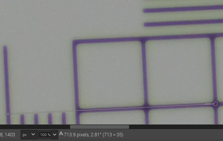
I took leftmost frame

and rightmost frame

You see 0.01mm resolution micrometer. I measured 360 pixel between two big divisions 10*10µm=100µm apart. And I counted between 4 and 6 pixels (only!) movement between a markers leftmost and rightmost position. For being on safe side let us assume the movement from left to right is 7 pixels.
First we can compute the operational range for the 300 steps, it is 2µm(!) in total:
$ echo "scale=6; 100/360*7" | bc -ql
1.944439
$
Dividing by 300 (steps) gives 6.5nm(!) average step width:
$ echo "scale=6; 100/3607/3001000" | bc -ql
6.481000
$
I built a Leo frame around a 1$ mirror from drugstore.
And I created 4 Lego springs from ballpoint springs:
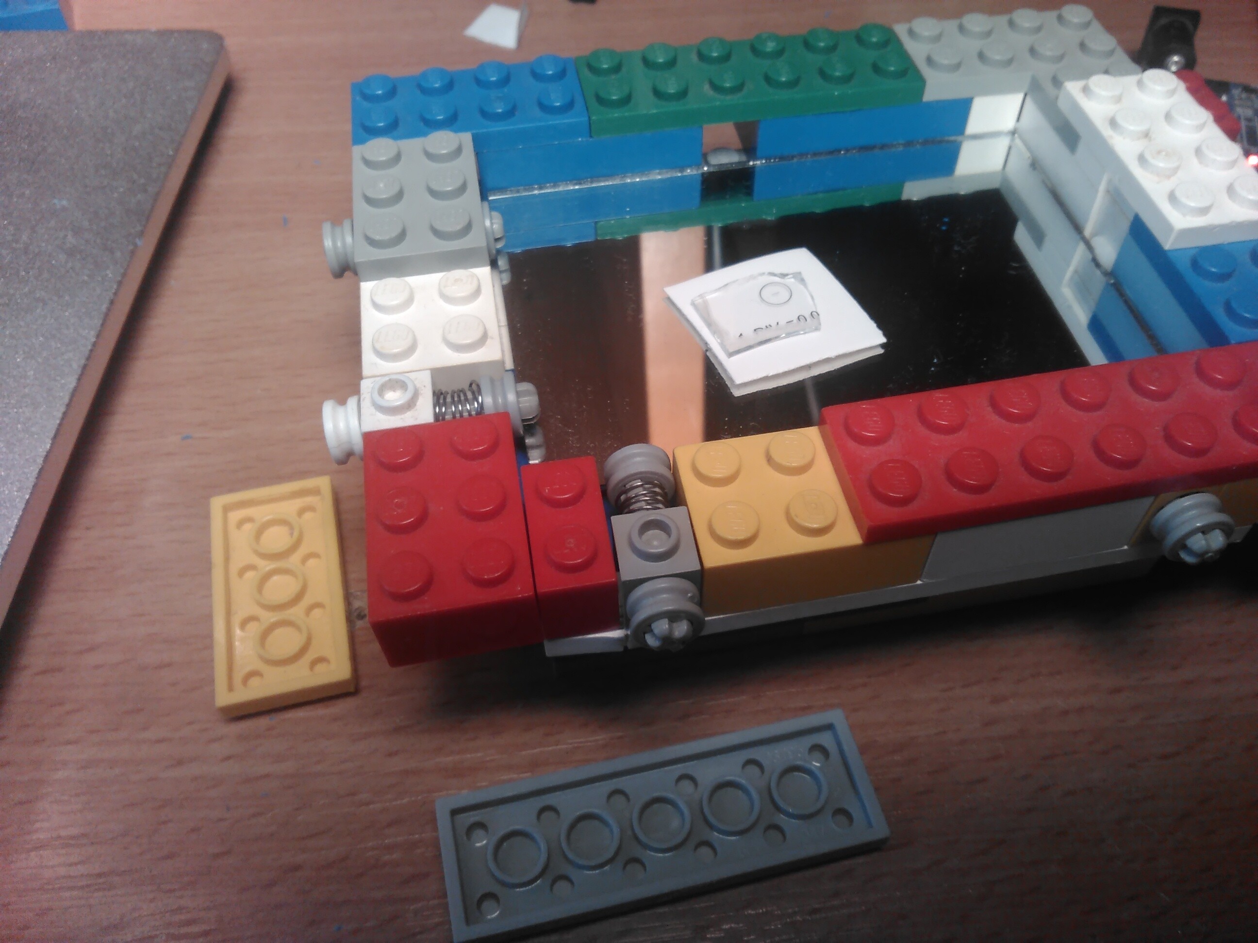
I did drill 2mm diameter holes into the Lego pieces with my Dremel, screwed the stepper motor with M3x16 screws:

Because the motor shaft is not in stepper motor middle, I can make motor sit at an arbitrary angle by just screwing left and right screws in or out a bit:

The Lego piece with flat top (it moves on a flat top piece below it as well) did not reach the mirror at the given angle, so I just inserted a 1.5mm thick small piece of plastic between movable Lego piece and mirror:

As you could see above, the angle of stepper motor can be increased arbitrarily. That will reduce the step width below 1nm, but I have no idea on how to see/verify that, as the Raspberry Pi camera cannot sharply display stuff even in low single digit micrometer range. Maybe my 0.001mm electronic micrometer can help with that later:
Today I learned that it is safe to power two 28BYJ48 stepper motors with half-stepping from USB powered Arduino 5V power rail. So the whole xy positioning table consists of some Lego pieces, small mirror, two stepper motors, two ULN2003 drivers and an Arduino Uno!
https://forum.arduino.cc/index.php?topic=648859.msg4377804


)
)