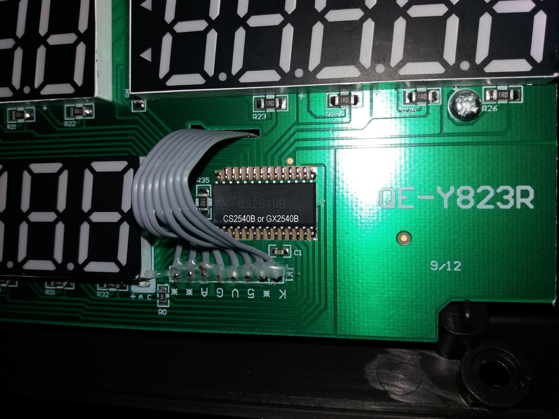
I have a scale purchased from China that uses a display with 3 blocks of 7 segments controlled by an integrated circuit that is GS2540B or CS2540B, please see the photo in the link below. Could someone tell me a library on how to use these displays with this controller integrated circuit in the Arduino UNO ?
I saw that they communicate through 8 wires. In fact, the scale has 6 displays, being identical integrated circuits. But I only need 1 integrated with 3 displays. That is, this detail is not important because I just don't use the second block.
I haven't found anything so far about this integrated circuit. But I think it should just be a driver equal to a ULN2003 or similar. I'll try to make a visual survey of the trails and draw the circuit. In the meantime, I'll keep an eye out here in case anyone else can help.
I've already typed in google CS2540B and GS2540B and nothing. It appears to be a unique chip. I need to try something. I need a code and a way to make the wire connections.
In my first post reported that there are two boards, each with 3 7-segment displays. For this example using the MAX7219 there would be 3 wires for each integrated circuit. Here I saw that the flat cable has 8 wires. So I think it's 3 wires for the integrated circuit on board 1 + 3 wires for the integrated circuit on board 2 + GND and VCC = 8 wires. Now, of course, I'll have to guess the connections. Good occupation for a Sunday.
I don't have much knowledge but I think with a little help I will have some results. See: This is the controller board. What matters is just the J3 connector. With the multimeter (that's all I have) I was able to identify 3 pins. Another 3 I believe are what I wrote. There are 2 left that I don't know what they would be. I'm not going to use Arduino UNO because its outputs are 5 volts. I have a Wemos D1 mini here. It remains to be seen if I am on the right path and what code I could use for testing. I don't intend to go too far. If it doesn't work, I'll put it aside and buy a MAX 7219 module.
To help there is nothing written on the body of the displays about cathode or anode. I connected the Wemos mini D1 like this: D7 = Data, D8 = CS and D5 = Clock. I used MAX7219 and 74HC595 library examples trying to get lucky and nothing. No segments lit. I didn't connect DK or BL.
I returned the displays to the scale and they are fine. That is, turning on the way I did not burned. Less bad. Apparently it will be difficult or even impossible given the few resources I have. Like I said, if it doesn't work out I'll buy a MAX7219. Does anyone have any ideas ?
Do you have the device that it plugs into? Can you make it operate? Scope the connections.
Have you traced the PCB traces and produced a block diagram?
What would you do with a MAX7219? You can't connect it directly to the display, you would have to either use a new display that you have schematics for, or reverse engineer all the LED module connections and possibly desolder all the other parts.
What is really going on here, you have a surplus board and you want to save some money by using it, or else it has some special shape/outline/segments that would be difficult to reproduce using off the shelf parts?
Because it seems like you don't understand the high level of difficulty. Which means, help will be arduous and non rewarding.