ian332isport:
You are not so much limited by the number of bytes you send, but you are limited to 8 bits of data per byte (8N1). This is a maximum of 0xFF in HEX, so you can't send 0x00F00352.
OK this give me 255 different trains. I think that will do. If not, i think there are ways to combine (and split) the code so i can have some more!
I have a question about a library for CAN bus but this is not the place to discus that!
You also can't send the word True. You can send the ASCii code for each letter though.
My thoughts got mixed up with another language. The word i want to send is LOW of HIGH. Maybe somthing else like 0xFF. Any suggestions for a token?
Because off the need for a master-slave network i need to create a token. The slave (or the master) that has the token can speak on the bus. Otherwise all slaves will send their data whenever they feel like it and it will cause collisions.
But over the past few days i've been thinking. The purpose of the network is that the slaves read signals that have to be collected by the master. So if the master constantly needs to check all the slaves for data the bus maybe busy when there actually is data to be send. Maybe i need another aproach?
Some info: the LIN master will be connected in a CAN bus network. So it needs to listen for CAN messages & act as the LIN master.
You may be able to get a token system working, but it's probably better to allow any device to send as long as the bus is clear.
If the Rx line (and therefore the LIN bus) is high, the bus is clear. You need a system that checks to see if the bus is high before you send any data. As soon as you start sending, the other devices will see the bus is busy and won't send until it is.
This was quite tricky, (for me) to get working with the MCP2003/2004 chips. I did get it working for the most part, but it wasn't 100% reliable. This is why I chose to use the Melexis TH3122 chip instead. This chip detects when the bus is busy and has an output on one of its pins that can flag to the Arduino that the bus is clear. I used this signal to trigger an interrupt that changed the state of a 'clear to send' flag.
My current system stores any outgoing messages in a circular buffer, and sends them as soon as the bus is clear.
ian332isport:
You may be able to get a token system working, but it's probably better to allow any device to send as long as the bus is clear.
If the Rx line (and therefore the LIN bus) is high, the bus is clear. You need a system that checks to see if the bus is high before you send any data. As soon as you start sending, the other devices will see the bus is busy and won't send until it is.
This was quite tricky, (for me) to get working with the MCP2003/2004 chips. I did get it working for the most part, but it wasn't 100% reliable.
Can you tell me how you did this?
This is why I chose to use the Melexis TH3122 chip instead. This chip detects when the bus is busy and has an output on one of its pins that can flag to the Arduino that the bus is clear. I used this signal to trigger an interrupt that changed the state of a 'clear to send' flag.
My current system stores any outgoing messages in a circular buffer, and sends them as soon as the bus is clear.
The documentation i found on this chip says it is a K-bus transceiver. I did not find a lot of info about this bus? Do you know the specs of the bus? Like number of nodes, buslength, speeds,...? I also did not find a store where i can buy this chip? Are they discontinued and do you know an alternative?
I have tried few codes and schematics from the internet but nothings seems to work.
It may be that I supply too low current for MID to work but I don't think this is the case since I also tested my setup in car and I got nothing.
Note few things:
My 12V+ is from power supply and it has 2 calbes in it so probably no GND.
I have no idea what to do with Vren but when I connect it to 5V Tx flashes.
I tried measuring IBUS signal coming out from MID but nothing shows up on my $2.5 multimeter(may be too slow?)
I don't have usb<->serial adapter yet so for now I am just cheking tx/rx leds on arduino.
Btw what are the differences between 2025 and 2004 mcps?
I test it with ians code as I found it to be simplest:
mp1337:
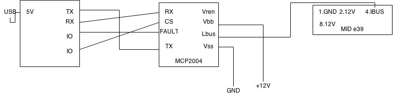
My goal is connect to MID display using MCP2004 and Arduino.
I have tried few codes and schematics from the internet but nothings seems to work.
It may be that I supply too low current for MID to work but I don't think this is the case since I also tested my setup in car and I got nothing.
Note few things:
My 12V+ is from power supply and it has 2 calbes in it so probably no GND.
I have no idea what to do with Vren but when I connect it to 5V Tx flashes.
I tried measuring IBUS signal coming out from MID but nothing shows up on my $2.5 multimeter(may be too slow?)
I test it with ians code as I found it to be simplest:
void readIBUS() {
if (Serial.available()>0){
byte INbyte = Serial.read();
}
}
I'm no expert but it seems that with this sketch you try to reed a signal from the display? Don't you send commands to it and then read the response message?
The datasheets for LIN components sugest you need to determain the master fysically with a diode and resistor. There is no such connection in your schematics?
I'm also not sure what the task of the Vren pin is. The datasheet shows a voltage regulator but as the input of it? I hope Ian can help us out!
When I connected mid to my car(which was running) it was off until I have clicked a button on on it(for example BC button, but no mute/turn radio on button since I disconnected radio) so my guess is and I am almost sure that I am right MID sends commands to a car and when the car responds with whatever MID turns itself on and shows response.
Having what I said in mind I tried sending sample text to MID from arduino with radios id but it didn't work. I was using code from the internet to do that.. I started to analyze it and found too many bugs so I figured I will just try to read codes from clickng buttons on my MID - and this is what I am trying to do.
I didn't see part about setting device as master - will try that later, but I think it doesn't matter if its slave or master if we want to receive data unless lin specifies that there has to be master device in the network but I didn't check yet.
mp1337:
I have no idea what to do with Vren but when I connect it to 5V Tx flashes.
Vren is an output that can be used to drive the enable pin on some voltage regulators. You don't need to use, and it can be left disconnected.
I tried measuring IBUS signal coming out from MID but nothing shows up on my $2.5 multimeter(may be too slow?)
The IBUS line will sit at 12v (or car battery voltage) when idle, and gets pulled low during communication. On the car, the instrument cluster is the master, and pulls the bus line high. If you are testing out of the car, you need to pull the bus line up to 12v through a 1k resistor, or it will just float and cause problems.
Btw what are the differences between 2025 and 2004 mcps?
The main difference is the 2025 contains a 5v voltage regulator that can supply 75mA of current. You can use this to power the Arduino if you like. I ran an Arduino Nano from this without any problems.
I test it with ians code as I found it to be simplest:
That piece of code will not work very well. It will read bytes from the IBUS, but can't detect the end of an IBUS message.
I connected my IBUS through pull up resistor and a diode as documentation says and I got -12V(in fact -11.80~~ if that matters_. Is that correct or did I insert my diode wrong way?
Still no luck getting anything from MID diode or no diode
I know this code won't work very well but it is so simple that nothing can go wrong there and I just need to test my circuit before I go on with writing proper code...
If you can, please post some sample message with check sum that I can test sending with later.
I connected my IBUS through pull up resistor and a diode as documentation says and I got -12V(in fact -11.80~~ if that matters_. Is that correct or did I insert my diode wrong way?
I wouldn't expect to see a negative voltage regardless of the diode orientation. More likely the meter leads the wrong way around.
I know this code won't work very well but it is so simple that nothing can go wrong there and I just need to test my circuit before I go on with writing proper code...
If that's all of your code, you won't see anything. It will receive some bytes and store them, but won't display them or give you any indication of what's going on. If you have more code, please post it.
What is your ultimate goal ? Are you just trying to send text to the MID display, or something more involved ?
Yeah - I connected the meter ok - without diode it was positive.
My final goal is to replace e39 stock radio with nexus 7 android tablet without loosing radio and OBC functions.
I am using MID only for testing my circuit so I don't have to sit in car at night when it is freezing cold.
Yes - this is all the code I use. I figured RX diode on arduino should flash on any input, right? I can't use debug till Monday when I will receive USB<-> Serial converter.
Anyway. I wen't to car and hooked it up like this
Car <-> Breadboard with arduino and mcp<-> MID.
So basicly mcp and arduino should act like a proxy between these two.
I made one mistake connecting all 12V+ lines from MID to one 12V+ output from car probably blowing some fuse as it no longer works.
Before I have done that - I tested this setup with the code I postead earlier and no flashing diodes - no nothing.
I measured IBUS in car and it was 10.8V(again my multimeter is super cheap) and was dropping to 10.6 when I pressed something(meter to slow probably - correct me if I am wrong).
I would suggest starting with the basics. Just hook up the MCP/Arduino circuit to the IBUS line on the car and make sure you can read IBUS messages before trying anything else.
For testing in the house, I use a piece of software called Navcoder and an interface from Rolf Resler. I'm not sure you can use the MID on its own, as it probably won't function unless it can talk to the instrument cluster. It will probably send a few messages when you first power it up, but unless it gets a reply from the instrument cluster, it will probably stop transmitting. Most IBUS devices announce themselves on the bus when they power up. The car should see this message and periodically send out 'are you still there' messages that the device must reply to. If the car doesn't get a reply, it assumes the device has gone faulty and stops talking to it. I think it retries three times before it stops talking.
I don't think you can use the Tx / Rx led's to look for serial activity on the Tx / Rx pins. These led's only flash when data comes in/out of the USB port (assuming an UNO or Nano - not sure about other boards).
You'll need a logic analyser to see the bus traffic. You won't see anything useful on a multimeter.
I have soldered a MCP2004 to a devboard of Arduino Due, but I miss a diagram of how to connect it to arduino. Please laugh at a rookie but share with me a diagram and a working sketch to read/write Lin-bus.
Please refer to a datasheet of the circuit and use the program I posted before with usb to ttl converter connected to output ibus messages using arduino. If you have any particular problem we can help you, but we cannot do all the work for you
Ian,
I had little bit of delay with the project because of university semester ending, but just got back on track.
I have got arduino debug via software serial working and my question is: should I cross rx/tx when connecting MCP to arduino?
I have 2 mcps and tested both with ardunino and connected directly to usb ttl converter but nothing happens. I think I may have broken the mcps before while testing with MID but no idea how to check that.
Btw fun story. Just spent about hour testing the circuit and my car won't start now so I had to leave it at parking lot where I was testing(2km from home). No idea what happend.
Well,
I connect everything the same way I did before(please check schematics that I posted) but instead of MID i use GND, 12V and IBUS from MID connector. I need USB to TTL converter to use softwareserial as debug.
I have tested everything on 2 MCPs and did the same thing in home with MID.
Both cases - I haven't got any output on my computer except from --IBUS read test-- from your program.
Unfortunetly I can't check voltages on every wire because it is really a pain in the ass working in a car with all this stuff, but I checked output on voltage regulator pin of mcp and it was about 8V.
Edit: I just checked some circuits from other people that were using MCP2004 and some of them mention pull up resistors on RX and WAKE pins. I will check if this is the case tomorrow morning.
mp1337:
I haven't got any output on my computer except from --IBUS read test-- from your program.
Can you post your complete sketch, so I can see how you are reading the iBus ?
I checked output on voltage regulator pin of mcp and it was about 8V.
Assuming you are using the MCP2004, you don't have a voltage regulator. That was only on the MCP2025. The voltage regulator pin is simply an output that goes high to enable an external voltage regulator that has an enable function.
Edit: I just checked some circuits from other people that were using MCP2004 and some of them mention pull up resistors on RX and WAKE pins. I will check if this is the case tomorrow morning.
I'd ignore the wake pin for now. You shouldn't need to pull the Rx pin up. In some circumstances, you need to pull the iBus line up to 12v with a resistor, but generally only when you are outside the car. The instrument cluster is the master inside the car, and will already be pulling the bus high.