Hello!
I'm currently working on a project (boat tiller) involving this linear actuator https://www.smcpneumatics.com/LEY16LB-200.html.
I am connecting A/B from actuator to a BT6600 driver. The actuator is driven by a joystick. All work as expected, but, there is a problem. When the actuator is de-energized, it can be moved by hand, and thus changing the 0 (zero) position reference (which is half the distance of the rod travel). So if this is changed, before the system starts , the actuator rod must be manually adjusted to this 0(zero) position.
Can this be done via programming? The actuator has its own encoder, but i cant figure out how to get info to use it.
Post a data sheet for the actuator that you have. Include the full part/model number so that we know what options that the actuator incudes and how the encoder is wired.
Not only is it done, it is very common. It is common practice to set a reference point when initializing a stepper system. It is called "homing" the motor. Use an included encoder or an external switch (mechanical, optoelectronic, magnetic).
Some ideas that come to mind:
A brake to prevent motion when powered down.
A calibration position, so drive the servo fully in or out and use that as a reference point. You could use reed switches, limit switches, what ever takes your fancy to confirm it has reached reference.
I assume there is a pivot point for the tiller? Can you directly connect a POT and reference the wiper? This would give full angular feedback when ever you want it. You could belt drive it or gear drive etc if it’s easier.
Absolute linear encoder on the linear servo for feedback if you have deeper pockets. Or an absolute rotary encoder on the pivot point… again £££
A tiller doesn’t lend its self to monitoring easily, is this a model boat?
SMC LEY 16LB 200M. I dont have data sheet for this actuator, unfortunately.
I rather not ușe any limita switches, i want tot keep the system as simple as possible. It does have an encoder, but ,as i said, i cant figure out how tot use that information because i have no manual for this actuator. It has 12 wires to the motor+encoder, so i could find A+/A- and B+/B- to connect with the driver. It also have Com A and Com B wires (found in a presentation manual) but, because my understanding is very low in this field, I cant find a way to use those Com ports.
Contact the manufacturer and ask for one.
Then don't. Use a switch to detect the zero position(centered). You can find the center position at the start of the program by moving the tiller a bit to the left, then the same amount right, each time looking for that switch. If not found, increase the amplitude of the motion until you find the switch. Then reset all the logic because the tiller is now centered.
Sure there is a problem if the tiller is all the way to one end, but you can sort of center the tiller yourself and then start the program.
Post the presentation manual. It’s a start.
A and B pulses are easy to code, the sample rate of the Arduino is a bit slow for an incremental encoder however, unless you move it slowly or have a low PPR value. A shield may have an integral HSC. A+ A- B+ B- is states not wires or pins. Absolute encoders don’t give pulses out only absolute information, so if your built in encoder is incremental you’ll still need to use a known reference to set up your datum, manual or not.
Thanks for ideea, that will be plan B for the moment.

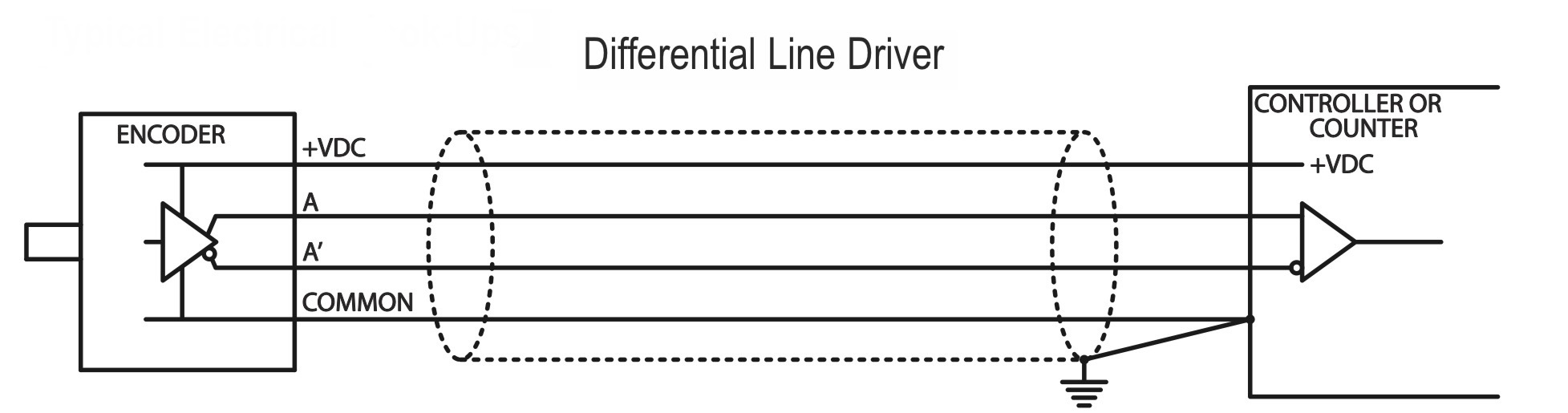
As suspected it’s differential signals from channels A and B of an incremental encoder. So Ā is the reference to a comparator and A is the signal to compare. If A>Ā then it’s a logical 1 to the μC. If A<=Ā it’s a logical 0. Channel B is the same but 90 degrees out of phase. The phase shift lets you decide direction of travel, not just speed and distance traveled.
If your tiller moves to position concisely after you have manually calibrated zero I would suggest either the feedback is working, or it is defaulting to just stepping on a set number of times, a stepper motor tends not to loose steps as they are synchronous, so drift isn’t a big issue. I’m sure I read somewhere it’s using a stepper motor but I stand to be corrected.
You can use the comparator in the Arduino by setting the ADC to reference external voltage when that analog channel is being compared by the multiplexer, but it still won’t help you to find a zero the position. For that you need a datum method such as travelling to an extremity, a switched input, or adding an incremental encoder etc to the circuit.
This topic was automatically closed 180 days after the last reply. New replies are no longer allowed.