Lion head with animatronics eyes and eyelids

Hello Arduino community !
I’m Lily and I am a complete beginner with programming. It would be awesome if I could benefit from some guidance to finish my ongoing project: a lion head I made with resin, with animatronic eyes and eyelid (see pictures).

I took inspiration from other projects and tried to adapt it to mine. I went as far as I could in the process of programming and creating a circuit, and having my work checked would be truly great (I don't want to burn or break something...).

PROJECT DESCRIPTION
The eyes mechanism is 3D printed and uses 2 servos (picture above), that allow the eyes to move in all directions (x and y axis simultaneously, one servo per axis). It is controlled by a small joystick. The goal:

  • Pushing the joystick forward makes the lion look upward
  • Pushing the joystick backward makes the lion look downward
  • Pushing the joystick on the left (respectively right) makes the lion look on the left (respectively right).

For the eyelids, each eyelid has its own servo and are controlled by the same joystick used for the eyes. The goal:

  • Pressing once on the joystick closes both eyelids simultaneously, and then those eyelids reopen directly after that (without pushing on the joystick again)
  • If that is possible, when the joystick remains pressed, the eyelids remain closed as long as the joystick is being pressed on (if too complicated code-wise, never mind)

I did not build the eyelid mechanism yet, but I can make the respective servos move without being attached to it. I will personally have to adjust the angles of rotation of the servos later on for both eyes and eyelids to match with the expected range of movement of the mechanisms.

Finally, there is a switch to turn the circuit off/on.

WHAT WOULD BE HELPFUL FOR ME

  • My code: is it correct? Can it be optimized (= rewrite in a more effective way)?
  • My circuit: is it proper? Are they components that need to be added or moved? Are the connections in the right place?
  • The battery to use: is my calculation to find that out correct?

COMPONENT INFOS
Arduino Nano (A000005)

  • Operating voltage: 5 V
  • Input voltage: 7-12 V
  • Power consumption: 19 mA
  • DC current per O/I pins: 40 mA

Micro servo (9g) SG90

  • Voltage: 4,8-6V
  • Limit angle: 120°
  • Work speed (empty): 0,12 s/60° (4,8 V) and 0,13 s/60° (6 V)
  • Idle current: 5 mA (4,8 V) or 6 mA (6 V)
  • No load running current : 100 mA (4,8 V) or 120 mA (6 V)
  • Stall current: 700 mA (4,8 V) or 800 mA (6 V)

THE CIRCUIT
To make it "visually easier", I took a shot of one component individually then the full circuit (PDF normally attached to this post)
Circuit pictures.pdf (683.4 KB)
.

MY BATTERY CALCULATION
Arduino (x 1): max voltage of 5, or 12 V? (not sure of this)
Current: 19 mA

Servo (x 4): max voltage 6 V
Current: 800 mA

Thus 800 x 4 + 19 = 3219 mA = 3,2 A

Battery: 6 V with 3,2 A. Is a 6V battery good to use?

CODE

//add the servo library
#include <Servo.h>

//define our servos
Servo servo1; //EYES horizontal movement
Servo servo2; //EYES vertical movement
Servo servo3; //LEFT EYELID
Servo servo4; //RIGHT EYELID

//define joystick pins
int joyX = 0; //analog pin connected to X output
int joyY = 1; //analog pin connected to Y output
int SWpin = 2; //digital pin connected to switch output

//variable to read the values from the analog pins (X et Y)
int joyVal;
//variable to read the values from the digital pin (switch)
int SWval;

void setup()
{
  //attaches our servos for EYES on pins PWM 3-5
  servo1.attach(3);
  servo2.attach(5);

  //attaches our servos for EYELIDS on pins 6-7
  servo3.attach(6);
  servo4.attach(7);
  pinMode(SWpin, INPUT);
}

void loop()
{
  //read the value of joystick (between 0-1023) for EYES
  joyVal = analogRead(joyX);
  joyVal = map(joyVal, 0, 1023, 0, 180); //servo value between 0-180
  servo.write(joyVal); //set the servo position according to the joystick value

  joyVal = analogRead(joyY);
  joyVal = map(joyVal, 0, 1023, 0, 180);
  servo2.write(joyVal);

  //read the value of joystick for EYELIDS
  SWval = digitalRead(SWpin);
  if (SWval == 1) // or while?
  {
    servo3.write(90); //angle to run to close the eyelid: to be adjusted once connected to the mechanism
    servo4.write(90);
  }
  else
  {
    servo3.write(0);
    servo4.write(0);
  }

  delay(15);
}

I can’t wait to learn more and I hope that this project will look interesting for some. Thanks a lot!

If you really want help, tell us if the code works as you want and if not, what is different. Same with pictures. No information there. Draw a real schematic and take a picture of it and post it.
Please read and follow the suggestions at the beginning of the forum that tells how to get the best help.
Good luck.
Paul

The code doesn't compile so it definitely isn't correct. Maybe 'servo' should be 'servo1'?

6V is fine for the servos but batteries aren't specified with a number of Amps so you need a bit more work to decide on the type of battery. E.g. rechargeable or not? How long must it last on a charge or before being replaced? I'd probably use 5 x NiMH rechargeables but there are plenty of other options,

Arduinos work at 5V via the 5V pin (best power) or 7V-9V via Vin (not really recommended) so 6V is wrong. I would use a 5V DC-DC converter from the the 6V battery to power the Nano.

Show the compiler messages.

Not my code, not my problem. Let the OP read their own messages.

Steve

Ok, I will take a look into crystal ball to find a solution

Good morning Paulpaulson and Slipstick,
Thank you for your replies !
My bad for the schematic, I will prepare this.
I will adjust the "servo" VS "servo1" mismatch and make the circuit run with the suggested battery by Slipstick. I will see how it turns out and I will post an update (hopefully it will work).
Have a nice day !

Good evening Arduino community,
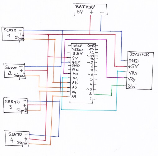
Following Paupaulson request, I prepared the schematic for the circuit (it is new to me so I hope I presented all the information needed for evaluating the project):

Additionally, with the remark from Slipstick, the code is now running and I could upload successfully the code on the Arduino board.

Notes:

  • I shifted to Arduino Uno (instead of Nano) because I faced a problem with the transfer cable. I had to change the number of some pins to match with the new board, so I put below the code again with the adjustment of those numbers
  • I also removed the switch
//add the servo library
#include <Servo.h>

//define our servos
Servo servo1; //EYES horizontal movement
Servo servo2; //EYES vertical movement
Servo servo3; //LEFT EYELID
Servo servo4; //RIGHT EYELID

//define joystick pins
int joyX = 1; //analog pin connected to X output
int joyY = 0; //analog pin connected to Y output
int SWpin = 2; //digital pin connected to switch output

//variable to read the values from the analog pins (X et Y)
int joyVal;
//variable to read the values from the digital pin (switch)
int SWval;


void setup()
{
  //attaches our servos for EYES on pins PWM 2-3
  servo1.attach(2);
  servo2.attach(3);

  //attaches our servos for EYELIDS on pins 4-5
  servo3.attach(4);
  servo4.attach(5);
  pinMode(SWpin, INPUT);


}

void loop()
{
  //read the value of joystick (between 0-1023) for EYES
  joyVal = analogRead(joyX);
  joyVal = map(joyVal, 0, 1023, 0, 180); //servo value between 0-180
  servo1.write(joyVal); //set the servo position according to the joystick value

  joyVal = analogRead(joyY);
  joyVal = map(joyVal, 0, 1023, 0, 180);
  servo2.write(joyVal);

  //read the value of joystick for EYELIDS
  SWval = digitalRead(SWpin);
  if (SWval == 1) // or while?
  {
    servo3.write(90); //angle to run to close the eyelid: to be adjusted once connected to the mechanism
    servo4.write(90);
  }
  else
  {
    servo3.write(0);
    servo4.write(0);
  }

  delay(15);


}

Unfortunately for me, nothing happens (note : the power supply is from the USB cable connected to my laptop as I didn't received yet the battery suggested by Slipstick).

I tried also with the code of a programmer for a simple circuit with just one servo and no joystick. With this, his code works properly (moving servo), so no abnormality in the process of uploading.

Using the same system, I tested each of my 4 servos individually. All work.

I checked additional tutorials as well, and found a recommendation of using the VIN pin to power servos. I wonder if this should be applied to my case or not because I read different ways to proceed from different tutorials.

I checked that there were no poor contact in my circuit.

Maybe my mistake in my circuit is very stupid... I am a beginner and I intend to change that.
Any suggestion on how to make my project work would be very much welcome and I hope not to cause any trouble.

From the code your servos should be on digital pins 2, 3,4 and 5 NOT analog input pins A2, A3, A4, A5 as your schematic shows. Which is it? If they're really on A2, A3 etc then that explains why they don't work. It's a bit of a giveaway when SWpin = 2 and servo1.attach() is also 2.

And PC USB is not enough to run 4 servos (most are rated at 0.5A and one servo can use more than that). There's a real danger you could damage the PC.

Steve

Hello Steve,
Many thanks for having taken the time to share those helpful recommendations !
As I should avoid using my PC to power that circuit (thanks for making me avoid a catastrophy...), I will proceed to the new tests as soon as I receive the components you advised me to find for power supply.

This topic was automatically closed 120 days after the last reply. New replies are no longer allowed.