Logic level mosfet not activating correctly

I'm trying to turn a 12V motor on/off using the logic level n-channel mosfet FQP30N06L activated by an Arduino Uno digital out.

However, I'm getting nonsensical results. I thought it would be as simple as wiring the digital pin to the mosfet gate, drain to motor/12v, source of ground. Right? Very basic circuit.

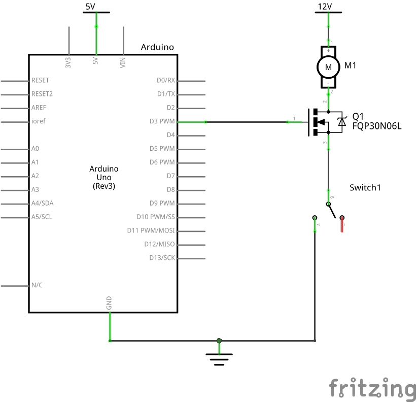
However, this did nothing. And no, it's not the switch. I confirmed by Arduino was outputting either 0V or 5V, and 12V was across the mosfet, but either way the mosfet would not activate.

So I simplified the circuit and removed the Arduino entirely, and even disconnected the gate like:

And now the mosfet activated, but was stuck on active. If I then wired the gate to +5V or ground, it would stay active.

What's going on here? I tried swapping out a new identical mosfet, but found the same results. I did a diode and resistence test on the mosfet to confirm it wasn't burnt out, and it passed, so I think the mosfet it good.

The datasheet for it says it's logic level, so the drain/source path should activate when the gate is 2.5V. Why can't I properly activate this mosfet?

I couldn't easily show it the schematic, but the motor/12v+ side is actually one of these 12v proportional motor controller with manual controls.

The motor and switch are actually directly connected to that and I'm trying to wire in an Arduino to it so it can programmatically turn that controller on or off by cutting the 12V red power cable running between that and the switch. And that works when I manually break the 12V red power cable using a switch, but doesn't work when using the mosfet.

Could that be interferring with the mosfet somehow? Electrically, the one side acts like a +12V line while the other acts like ground, so I don't see why that would be an issue?

I think I figured out part of the problem. I had my drain and source wired backwards. Now my Arduino can activate the mosfet, but only partially. If I set the motor controller to 100% power, wire the 5V lead directly to the gate, the the motor turns on at about 50% speed, so there's a big drop off.

Even worse, if I wire the gate to the Arduino's pin, then it can also turn the mosfet on and off, but when on, the motor only runs at about 25% speed, and the mosfet becomes extremely hot.

When is so much power being lost to heat in the mosfet? Is there a better mosfet I should be using?

Your MOSFET may be damaged. In future buy at least two of each part so that you can simply exclude damaged items.

1 Like

Or 5.

2 Likes

I'm not saying these are better, but your model is obsolete so.. these are last time I checked still available:

  • IRLB8721 THT, 5V logic
  • IRLZ44N THT, 5V logic
  • Si3460DDV SMD, 1.8V(!) logic

I try to wrap my head around this motor controller + the mosfet. How's all that connected or not?

But the other motor wire need to be connected to the controller MOTOR-

In your original schematic you have a switch between the source and ground, when the switch is open you have 12V connected to the drain via the motor and the gate connected Uno. The only thing preventing the 12V being presented to the Uno pin is the presumed high resistance of the MOSFET gate. This is dangerous, I can't say 12V will be presented to the Uno pin, but a design like this includes an unnecessary risk of damage.

If you must have a switch put it on the drain side of the MOSFET.

It seems to be a common beginner mistake to disconnect the ground to something without considering the consequences for the rest of the circuit, in this case a MOSFET with 12V on one of its pins and the only other connection being to a device that cannot tolerate 12V.

You also need a flyback diode across your motor.

3 Likes

So are you switching the 12V+ line with the mosfet? An N-channel mosfet should be used to switch the low side - the 12V- side. It's hard to tell from the picture, but it looks like the red wire is 12V+. If so, you may be switching the wrong wire.

Edit: No I guess the red wire goes to the switch. Anyway, just to clarify, I think this is the right wire to switch with the mosfet:

2 Likes

No series gate resistor.

No gate pulldown resistor.

Leaving the MOSFET's source pin floating when the switch is open. Shudder.

No flyback diode.

4 Likes

This topic was automatically closed 180 days after the last reply. New replies are no longer allowed.