Hello,
I had assembled a MIDI controller with two inputs and two outputs around an Arduino Mega.
I now want to replace the Mega with an ESP32 to benefit from a Bluetooth connection.
The MIDI circuit with the sockets and optocouplers is well integrated into my case and I do not want to make any modifications to it.
Would a logic level shifter * 4 be sufficient to adapt my MIDI circuit in 5V to the ESP IOs in 3.3V?
This will also allow me to go back during the debugging phase.
You can use a SN74HCT541N or a SN74ACT240N to go from 3.3V to 5V, connect Vcc to 5V
You can use a SN74LVC244A to go from 5V to 3.3, connect Vcc to 3.3V.
Do you need a schematic to show you how to connect them.
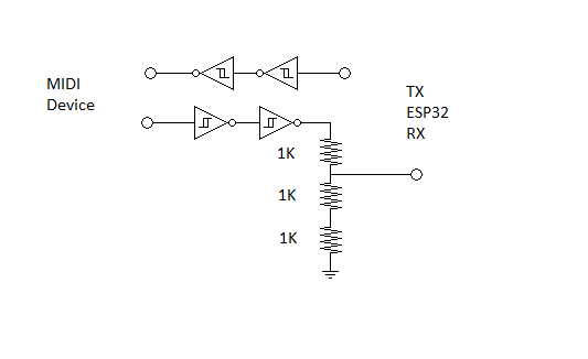
The spec for the output channel is to actually use a Schmitt-trigger (also for Midi Thru) so the best recommendation i can give you would be a 5v powered 74HCT14 and run it thru 2 gates.
The Spec was originally intended for no such clean digital signals and the Schmitt-trigger was meant to correct and square them out better. I use 74HCT04 IC instead and run the signal thru 2 gates. The provided 3.3v logic levels are easily enough to trigger the gate.
As you like. 14 pin though. There must be smaller packages available for something similar through.
On the input side you should just power the Vcc to the Opto-coupler with 3.3v and that will probably do the trick.
What kind of opto-coupler are you using now and with what resistor values ?
There should be no need to actually shift the logic level
That would really be the way to go though. (show us a picture of how gard it is to get to please)
What you could do instead on the input side is use 2 of the remaining gates on the 74HCT14 (or 04) run the signal thru 2 gates, and just use a simple voltage divider made up out of 3x 1K resistors to drop it's logic level down from 5v to 3.3v
I chose what was readily available from Digi-Key and Mouser. There are several other possibilities.
The 541 is nice because all the inputs are on one side of the IC and all the outputs are on the other. Makes it easy to use.
Keep in mind that on an ESP32 UART0 is connected to a USB to TTL converter, and UART1 can not be used without modifying the standard MIDI.h library (MIDI.begin() calls Serialx.begin() overriding any custom pins assignments, that would have to be disabled for ESP32 boards)
Using UART2 is the easiest, UART0 can used alternate pins if Serial.begin(BAUD, FORMAT, RX, TX) is called after MIDI.begin() with other pin assignments. TX on GPIO 1 will still work, but usually the rx pin (gpio 3) is not working because of the USB to TTL converter connection to it.
This is all for a ESP32(S) any of the other architectures and your guess is as good as mine.
All UARTs can be used though with modification to MIDI.h
Thanks Deva_Rishi.
I'll also look at your solution
The MIDI sockets and their associated components are placed on a larger PCB with other sockets and connectors: pedals (potentiometers and switches), power supply, rotary encoders, multi-switches and some additional components such as multiplexers to the control buttons.
I really don't want to intervene on this board.
Understandably so, for the input it would really be just connecting 3.3v to the pullup of the Opto-coupler, but since you have multi-channel level shifter already you may as well use gates/ports of that.
I'm back after a few days of thinking about my assembly. MIDI ports are not the only circuits for which I will need a 5V / 3.3V adaptation.
In audio world, multiplying adapters in a circuit is often the best way to multiply, squared, risks of malfunctions. It would be the same thing in embedded.
I think the safest way will be to rethink all my connections to work directly with a 3.3V processor and the opportunity to improve my circuits.
Thank you for your help and advices which helped me move forward in my thinking.