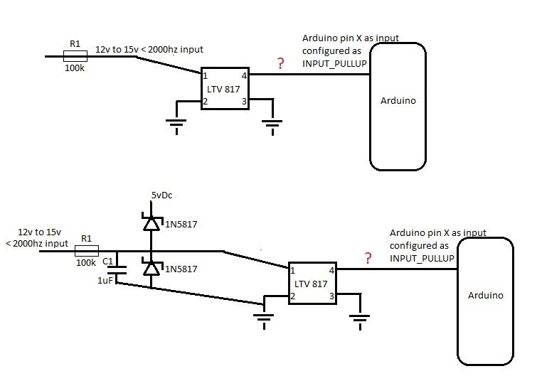
I need to measure rpm with the Arduino. I have found a conditioned signal that feeds from one module to the next that I can use to measure (see descriptive image below). At 1000rpm, the signal is 200hz, at 2000rpm it is 400hz and so on. The voltage value is ~14v and I would like to use high resistance to sample the signal as I do not know how impactful reading it will be. I'd also like to ensure the piggy back connection wire doesn't become an antenna for interference.
Is an optocoupler necessary or overkill? In reading/searching the forum, I have seen some suggest an optocoupler and others a simple conditioning circuit. I've also seen some use external ICs and other examples using the Arduino itself to determine a frequency, such as here Gammon Forum : Electronics : Microprocessors : Timers and counters .
That being said, I do not need a lot of granular accuracy, by that I mean having an update every 1/2 or whole second would be sufficient. My frequency will never exceed 2000hz and voltage (sans dirty voltage) will be 15v or below.
Is using the Arduino's timers and a digital signal conditioner like below sufficient? Also, how can I use the Arduino to generate/simulate the module signal I want to measure so I can bench test? Can I feed one output pin into an input pin without issue? I read some suggestions about using tone(), but I believe that's blocking and that wouldn't work if so. Guidance is appreciated.
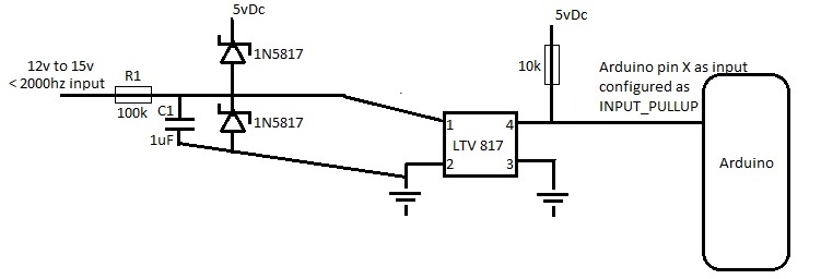
There isn't a whole lot of information resulting from searches I'm doing and I've never used an optocoupler before. Which circuit below (or neither) seem like the best choice and do I need a 10k resistor where the question mark is?
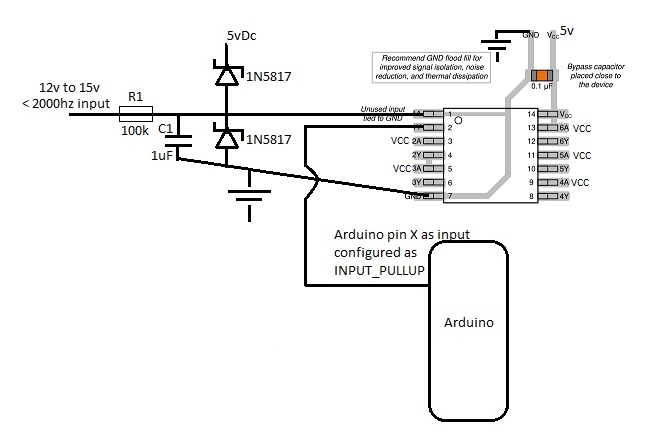
I would use a 74HC14 with a 100K resistor on its input. If powered from 5V the output will be 5V. If noise is a problem you can add maybe 100nf at the input of the gate. This will not load your existing signal as would an optocoupler would and bandwidth way beyond what you need. You can put a second in series with the first if you want a non inverted version of the signal. This uses the input protection diodes. at 50V you will be applying 500uA.
Please, learn a bit how to draw schematic and what symbols to use. Resistors look like fuse symbols and grounds on a the pins 2 and 3 look like battery cells...
1.Optocouplers are used for galvanic isolation, if you want to isolate what you are measuring, from arduino, then pins 2 and 3 shouldn't share a common gnd.
2. R1 (100K) resistance is too high to be able to drive optocouplers LED.
First, think about is galvanic isolation needed?
I do not need isolated grounds, only robust protection from automotive dirty voltage.
Mspaint doesn't offer a whole lot of options, however if there is a forum standard/well liked software for drawing circuits that I can download, I'm willing to give that a try if you can give me the name of the software.
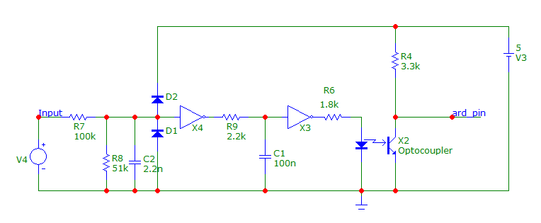
I draw this in MicroCap12, I use for simulation, but any electronics cad software could be used for these simple things..
If you want high input impedance, something like this should be good :
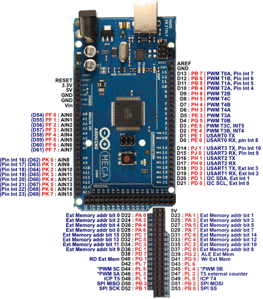
I'm looking at Nick Gammon's code from this link Gammon Forum : Electronics : Microprocessors : Timers and counters where it says "Frequency Counter sketch for Atmega2560" and it is way above my head. I'm not sure how he even defines the input pin (D47) that his notations indicate he is using in this sketch.
Can anyone recommend something more simplistic for frequency counting on my Mega? I need to count rising or falling edges, 30hz to 2000hz.
// Timer and Counter example for Mega2560
// Author: Nick Gammon
// Date: 24th April 2012

// input on pin D47 (T5)

// these are checked for in the main program
volatile unsigned long timerCounts;
volatile boolean counterReady;

// internal to counting routine
unsigned long overflowCount;
unsigned int timerTicks;
unsigned int timerPeriod;

void startCounting (unsigned int ms)
  {

  counterReady = false;         // time not up yet
  timerPeriod = ms;             // how many 1 ms counts to do
  timerTicks = 0;               // reset interrupt counter
  overflowCount = 0;            // no overflows yet

  // reset Timer 2 and Timer 5
  TCCR2A = 0;
  TCCR2B = 0;
  TCCR5A = 0;
  TCCR5B = 0;

  // Timer 5 - counts events on pin D47
  TIMSK5 = bit (TOIE1);   // interrupt on Timer 5 overflow
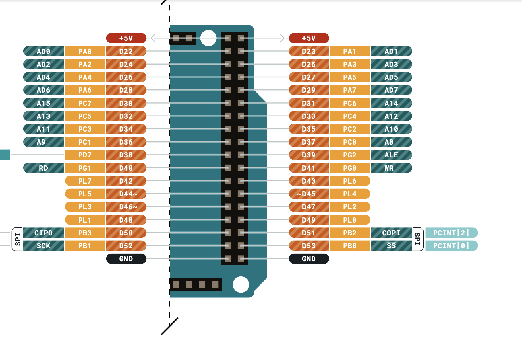
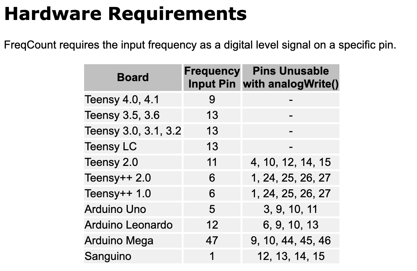
Nick did the work of looking up the Timer-5 counting input pin, and libraries like FreqCount look up handy special Timer counting input pins for the various devices:
Pins 6,7,8 will work fine for non-PWM uses, it's that the clock/timer that would normally manage the PWM for those pins will be in use counting your frequency events rather than
counting regular clock cycles.
Pin 47, right? You can use one of the other PWMs associated with one of the other timers to make an output frequency to feed back into pin47.
...was the same exact document, and the table at the top was the same. But it is not. On the Mega, FreqMeasure runs the Timer4 counter fast based on a clock, and uses the pin49/ICP4 to InputCaPture the Timer4 count when each cycle happens, versus FreqCount using 47/T5 Timer5 external clock pin to count the number of cycles in a certain interval of time. They are completely different mechanisms and, on the Mega, use different pins (and different timers).
Are you looking for something like a tone() example?
Tone may be suitable for this. I started to write my own very basic version, however for some reason my millis function isn't working now. I thought it was a problem with the timers, but I'm not using them now so I'm pretty confused as to why this is happening. My understanding is that millis is a built in method that should work out of the box? If the below works for you, I wonder if my Arduino is damaged?
unsigned long currentTimeStamp;
unsigned long serialLastWriteTimeStamp;

void setup()
{
    Serial.begin(9600);
    while (!Serial)
    {
      ; // Wait for serial to connect
    }

    currentTimeStamp = millis();
    serialLastWriteTimeStamp = millis();

    Serial.print("currentTimeStamp: "); Serial.println(currentTimeStamp);
    Serial.print("serialLastWriteTimeStamp: "); Serial.println(serialLastWriteTimeStamp);
    Serial.print("currentTimeStamp - serialLastWriteTimeStamp: "); Serial.println(currentTimeStamp - serialLastWriteTimeStamp);

}

void loop() {
  // put your main code here, to run repeatedly:

}