The ideal situation is to use the same logic voltage for all the parts of the project. Since almost all radios and sensors use 3.3V logic, the very best option is to use a 3.3V processor to interface with them.
ah okay so I will use a different board with 3.3v logic, got it.
One more question, how can I use the components that requires 5v to boards that have 3.3 v logic? Should I use a separate power supply? I don't want to replace many components as much as possible.
There are very few such boards. If you read the specs carefully, applied power voltage can be anywhere between 5V and 3.3V.
It is important that the voltage regulator on the board be "low dropout", which is the minimum voltage difference between input and output (0.04 V is common). A few older boards, mostly obsolete now, do not have a low dropout regulator and may give problems. The MPU-6050 is one, but you should avoid that anyway.
How about this board? Is this okay for the project that I am doing? which includes an ultrasonic sensor, oled, and maybe few LEDs and relays? and LoRa as well
I will try first using the logic level shifters using the Arduino Uno first and see if it works before I change to different board, I will post an update here soon. Thank you
I have a question again before buying parts. This is the only logic level shifter that is available to my place, and LoRa Ra 02 has a total of 7 pins (if include the 3.3 V) that I must connect which is not enough for the said logic level shifter. I apologize if this will be a stupid question but is it okay if the other pins will be connected to another level shifter if one level shifter is not enough?
The RA-02 normally only needs these digital pins connected;
SCK, MISO, MOSI, NSS, NRESET, DIO0.
VCC needs to be connected to a 3.3V supply capable of circa 100mA.
A common LoRa library by default does not use DIO0, its only needed if you want interrupt driven RX or TX complete. So you can get away with a 5 way logic level converter.
so to let me clear, I can use the level shifter by only connecting the SCK, MISO, MOSI, NSS, NRESET and will neglect the DIO0 (since it has no purpose atleast for my code) and also the 3.3 V supply which I will use a separate power supply for that? how about the ground?
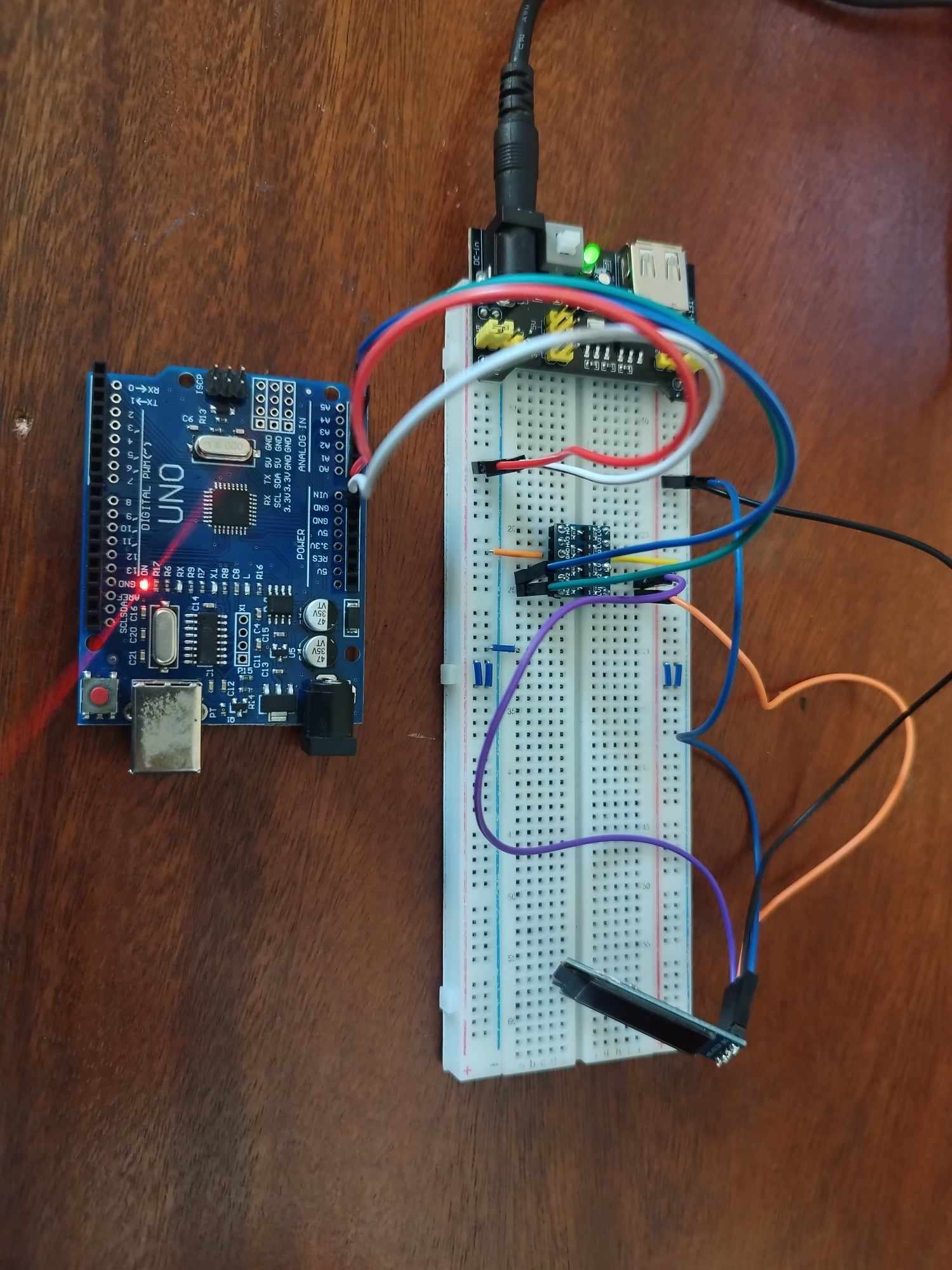
Hello everyone, the products have arrived and we tried to connect it and tested it. What we did was to test the parts individually with a separate power supply:
The link provided is the power supply that we use. The ultrasonic and oled works perfectly.
But the LoRa with a logic level shifter and with the said power supply selected in 3.3 v doesn't work. We used the example of the LoRa Library and the serial monitor prints: Starting LoRa failed!
Here is the code for the receiver, we supposed to test the sender as well but seeing that the serial monitor prints it means that there is something wrong with the connection.
#include <SPI.h>
#include <LoRa.h>

void setup() {
  Serial.begin(9600);
  while (!Serial);

  Serial.println("LoRa Receiver");

  if (!LoRa.begin(433E6)) {
    Serial.println("Starting LoRa failed!");
    while (1);
  }
}

void loop() {
  // try to parse packet
  int packetSize = LoRa.parsePacket();
  if (packetSize) {
    // received a packet
    Serial.print("Received packet '");

    // read packet
    while (LoRa.available()) {
      Serial.print((char)LoRa.read());
    }

    // print RSSI of packet
    Serial.print("' with RSSI ");
    Serial.println(LoRa.packetRssi());
  }
}