LoRa Ra-02 RX receiving random characters, or nothing at all

Hello everyone! I am fairly new to Arduino and we are doing a project with the use of LoRa Ra-02 to send and receive specific characters in order for the device to work.

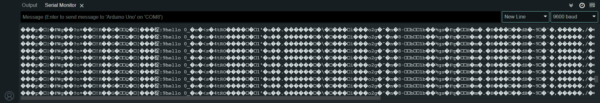
The thing is when the sender sent a message, the receiver just prints in the serial monitor random characters or sometimes not at all. The expected output is that the sender will send the characters 3, 2, 1 based on the measured distance and then the receiver will receive that and perform its functions such as printing on the OLED display and such. However, we can't do it due to the random characters that are sent to the receiver.

Here is the code for the sender and receiver,

Sender:

#include <Wire.h>
#include <Adafruit_GFX.h>
#include <Adafruit_SSD1306.h>
#include <SPI.h>
#include <LoRa.h>

#define SS_PIN 10
#define RST_PIN 9
#define DI0_PIN 2

const int trigPin = 3;
const int echoPin = 4;
long duration;
int distance;   

unsigned long previousMillis = 0;
const long interval = 5000;
const int MAX_DISTANCE = 60;

String lastSentCategory = "";

#define SCREEN_WIDTH 128
#define SCREEN_HEIGHT 32
#define OLED_RESET    -1
Adafruit_SSD1306 display(SCREEN_WIDTH, SCREEN_HEIGHT, &Wire, OLED_RESET);

void setup() {
  Serial.begin(9600);
  while (!Serial);

  if (!LoRa.begin(434E6)) {
    Serial.println("LoRa initialization failed. Check your connections.");
    while (1);
  }

  LoRa.setSpreadingFactor(12);
  LoRa.setSignalBandwidth(125E3);

  pinMode(trigPin, OUTPUT);
  pinMode(echoPin, INPUT);

  // Initialize I2C communication
  Wire.begin();

  // Initialize OLED display
  if(!display.begin(SSD1306_SWITCHCAPVCC, 0x3C)) {
    Serial.println(F("SSD1306 allocation failed"));
    for(;;);
  }

  // Clear the display
  display.clearDisplay();

  // Set text size and color
  display.setTextSize(2); // Increase text size
  display.setTextColor(SSD1306_WHITE);
}

void loop() {
  unsigned long currentMillis = millis();

  if (currentMillis - previousMillis >= interval) {
    previousMillis = currentMillis;

    digitalWrite(trigPin, LOW);
    delayMicroseconds(2);
    digitalWrite(trigPin, HIGH);
    delayMicroseconds(10);
    digitalWrite(trigPin, LOW);
    duration = pulseIn(echoPin, HIGH);
    distance = duration * 0.034 / 2;
   
    distance = MAX_DISTANCE - distance;
   
    String category = getCategory(distance);
   
    if (category != "Overlimit" && category != lastSentCategory) { // Check if category changed
      LoRa.beginPacket();
      LoRa.print(category);
      LoRa.endPacket();
     
      lastSentCategory = category;

      Serial.print("Sent category: ");
      Serial.println(category);
    }
    else if (category == "Overlimit" && category != lastSentCategory) {
      lastSentCategory = category;

      Serial.print("Sent category: ");
      Serial.println(category);
    }

    // Display distance or "Beyond Range" on OLED
    display.clearDisplay();
    display.setCursor(0, 0);
    display.println("Distance:");

    if (distance >= 0 && distance <= MAX_DISTANCE) {
      display.setCursor(0, 16);
      display.print(distance);
      display.println(" cm");
    } else {
      display.setCursor(0, 16);
      display.println("Overlimit");
    }


    display.display();
  }
}

String getCategory(int distance) {
  if (distance >= 0 && distance <= 20) {
    return "3";
  } else if (distance > 20 && distance <= 40) {
    return "2";
  } else if (distance > 40 && distance <= 60) {
    return "1";
  } else {
    return "Overlimit";
  }
}

Receiver:

#include <SPI.h>
#include <LoRa.h>
#include <Wire.h>
#include <Adafruit_GFX.h>
#include <Adafruit_SSD1306.h>

#define SS_PIN 10
#define RST_PIN 9
#define DI0_PIN 2

#define SCREEN_WIDTH 128
#define SCREEN_HEIGHT 32
#define OLED_RESET    -1

Adafruit_SSD1306 display(SCREEN_WIDTH, SCREEN_HEIGHT, &Wire, OLED_RESET);

void setup() {
  Serial.begin(9600);
  while (!Serial);

  if (!LoRa.begin(434E6)) {
    Serial.println("LoRa initialization failed. Check your connections.");
    while (1);
  }

  LoRa.setSpreadingFactor(12);
  LoRa.setSignalBandwidth(125E3);

  Wire.begin();

  if (!display.begin(SSD1306_SWITCHCAPVCC, 0x3C)) {
    Serial.println(F("SSD1306 allocation failed"));
    for (;;);
  }

  display.clearDisplay();
  display.setTextSize(1);
  display.setTextColor(SSD1306_WHITE);
  display.setCursor(0, 0);
  display.println("Warning:");
  display.display();
}

void loop() {
  int packetSize = LoRa.parsePacket();
  if (packetSize) {
    Serial.print("Received packet: ");
    display.clearDisplay();
    display.setTextSize(1);
    display.setTextColor(SSD1306_WHITE);
    display.setCursor(0, 0);
    display.println("Warning:");

    while (LoRa.available()) {
      char received = (char)LoRa.read();
      Serial.print(received);
      if (received == '1') {
        display.setTextSize(2);
        display.setTextColor(SSD1306_WHITE);
        display.setCursor(0, 15);
        display.println("RED");
      } else if (received == '2') {
        display.setTextSize(2);
        display.setTextColor(SSD1306_WHITE);
        display.setCursor(0, 15);
        display.println("ORANGE");
      } else if (received == '3') {
        display.setTextSize(2);
        display.setTextColor(SSD1306_WHITE);
        display.setCursor(0, 15);
        display.println("YELLOW");
      }
    }
    display.display();
    Serial.println();
  }
}

In rare cases, we've somehow managed to get our setup to send characters correctly using trial and error methods. We've tried everything from pressing reset buttons to swapping sender and receiver roles. The latest success involved stripping down the components to just the Arduino and LoRa module, using basic code, and once it worked, we gradually add the other components until it worked. However, once we remove the power supply and reassembled everything, it sends random characters or none at all.

Our Arduino board is a knockoff with a CH340G chip, and we're using an HC-SR04 ultrasonic sensor.

Here is the sample picture of what we see on the serial monitor of the receiver:

Please post a link to the product page for the radio module, for the Arduino board, and a wiring diagram of your setup.

The place to start is to get communications working with the simplest possible code, using only the radios, and the serial monitor for input and output.

Most responsible manufacturers of Arduino add-ons provide a wiring diagram and sample code to get you started. It is better to follow that advice than using "trial and error", which can end up destroying the equipment.

what host microcontroller are you using? a UNO?
what pins have you connected the RA-02 too?
the default setup for a UNIO is

// void setPins(int ss = LORA_DEFAULT_SS_PIN, int reset = LORA_DEFAULT_RESET_PIN, int dio0 = LORA_DEFAULT_DIO0_PIN);
LoRa.setPins(10, 9, 2);  // 10 for UNO, 53 for Mega
if (!LoRa.begin(866E6)) {
    Serial.println("Starting LoRa failed!");
    while (1)
      ;
  }

for an example transmitting a structure containing several data elements see post need-advice-on-a-home-project

as @jremington recommends test the LoRa communication and get it operational before connecting other components

Why use String when char is enough? Where is the terminating null character?

Your sure the Serial monitor output is from the receiver code you posted ?

Why does not "Received packet" appear in the output ?

here is the link for where I bought the components:

Arduino R3 board: UNO R3 board compatible with Arduino Development ATmega328P CH340 CH34 – Makerlab Electronics

Radio Module:

here is the connection of the components:

Yup, we used the sample sender and receiver code in the library of LoRa, and when we tested it, it worked successfully. But as we modify the codes and add the components, the higher the chance to send improper values making the receiver interpret it wrong.

What we mean by trial and error is that we use reset function of the Arduino or unplugging and replugging the power. Sometimes these actions seem to make it work temporarily, but over time the sender starts sending random characters or nothing at all. We also use the method of removing the parts down and start from scratch with basic sender and receiver code, and when it works, we gradually add components and upload modified code, we still experience inconsistent results of the values being sent.

Are you aware that the LoRa RA-02 module is 3.3V logic and you have connected it directly to a 5V logic level Arduino ?

Its not good to do that, it can cause problems.

Yes an Arduino Uno Clone (CH340G).

This is the connection of the pins that are connected to the RA-02

We did that as well, and seemed that the devices worked as intended but as we modify the parts and the code, it malfunctions by receiving random characters or sometimes not receiving at all.

I am a beginner to Arduino and coding as well, perhaps can you explain it to me further or maybe show me how to code it?

based on the wiring diagram that I showed in my reply to @jremington , I am aware that I connect the LoRa RA-02 module in the 3.3 V logic

Wrong.

Connecting the LoRa module to the 3.3V supply on the UNO does not turn the 5V logic level UNOs pins into 3.3V logic level ones.

Also on a lot of UNOs the 3.3V pin cannot supply enough current from the 3.3V pin to supply a LoRa transmitter.

my bad, it is when we strip all down all the components, and back to the basic code. And it seems that the packet data that being sent is still random.

We tested it earlier and record all the print in the serial monitor in the sender as well as the receiver:

Sender:
Sent category: 3
Sent category: 2
Sent category: 1
Sent category: 2
Sent category: 3
Sent category: Overlimit
Sent category: 3
Sent category: 2
Sent category: 1
Sent category: 2
Sent category: Overlimit
Sent category: 2
Sent category: 3
Sent category: 2
Sent category: 1
Sent category: 2

Receiver:
Received packet: 3
Received packet: 2
Received packet: 1
Received packet: 2
Received packet: 2
Received packet: 1
Received packet: 2
Received packet: 2
Received packet: 3
Received packet: v0 5' ҙ &h94r״ F i w r r
Received packet: 4r״ F i w r r r n%) 1b M #qHq 1 J m / T b   >)Z $ (P ,+ A B E&ύ _ p G}ciM8.o O|do <AC ͵ wc ٶ ! ܚ/  k*Z? c n £ u z_ 8 NIN w? z ;\ R Wo 7o۠ #K g  Q [ :92r3*/04 <@ v v0 5' ҙ &h94r״ F i w r r r n%) 1b M #qHq 1 J m / T b   >)Z $ (P ,+ A B E&ύ _ p G}ciM8.o O|do <AC ͵ wc ٶ ! ܚ/  k*Z? c n £ uz_ 8 NIN w? z ;\ R Wo 7o۠ #K g  Q [ :92r3*/04 <@ v v0 5' ҙ &h94r״ F i w r r r n%) 1b M #qHq 1 J m / T b   >)Z $ (P ,+ A B E&ύ _ p G}ciM8.o O|do <AC ͵ wc ٶ ! ܚ/  k*Z? c n £ uz_ 8 NIN w? z ;\ R Wo 7o۠ #K g  Q [ :92r3*/04 <@ v v0 5' ҙ &h94r״ F i w r r r n%) `1b M #qHq 1 J m / T b   >)Z

As you can see when we compare the sender and receiver serial monitor output, some of the values are not being sent, and some are printed in random characters. We unplugged it in the power source right after it printed random characters.

Ah I see so it is impossible to make a device where the first component uses the 3.3 V supply and the other component uses the 5 V logic level?

It seems like that is the case, even on the genuine Arduino Uno?

Its not impossible, but its a lost of hassle.

Much easier to use 3.3V logic level Arduinos.

So maybe I can use a separate supply to the other components that will use the 5.5 V while I use Arduino with 3.3 V logic level, is it possible or perhaps there are other solution?

To connect 5V logic to 3.3V logic, you can use a level shifter like this one:

However, one or both ends in your experiment may already have been damaged.

Oh okay, I will try it soon if it is available in my country.

I hope it is not, since the two LoRa still works or communicating without the components that uses 5v logic

A lot of characters there. Odd when the max length of a LoRa packet is 255 characters\bytes.

int packetSize = LoRa.parsePacket();
  if (packetSize) {
    Serial.print("Received packet: ");

Might be worth printing out the packetSize received.

This might be a dumb question but what is the ideal conversion? should I convert all the components that uses 5v logic to 3.3v logic or is it okay to convert the LoRa to 5v logic? And are all the pins of every component should be converted through the logic level converter?

sure I will add that later